[0018]According to one embodiment of the present invention, the pressing-on layer is implemented using a
ceramic material. The
ceramic material can have a high
thermal resistance capability, so that damage to the pressing-on layer does not occur even at high
processing temperatures of greater than 350° C., for example, preferably greater than 500° C. Because of a high
chemical resistance capability and / or a high
mechanical abrasion resistance, the use of a ceramic material can also prevent
contamination of the fiber-reinforced thermoplastic material to be pressed on by the pressing-on layer. Furthermore, through the use of a suitable ceramic material, health and safety hazards in the event of overheating of the pressing-on layer can be substantially avoided because of the thermal and
chemical resistance capability. For example, aluminum
oxide (Al2O3),
silicon oxide (SiO2),
magnesium oxide (MgO), or
chromium oxide (Cr2O3) and mixtures thereof can be used as possible
ceramic materials.
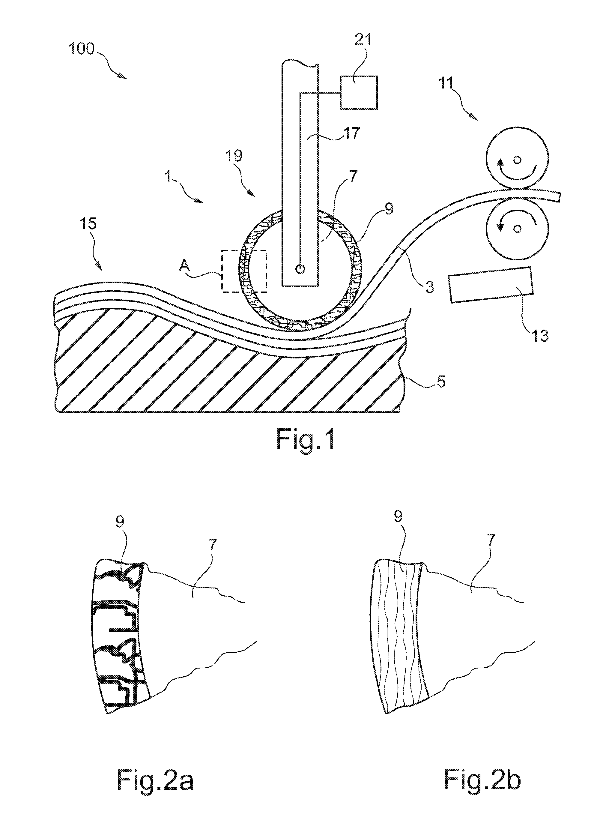
[0020]According to a further embodiment of the invention, the pressing-on layer is implemented such that it has a flexibility as a result of its structural design. In other words, the pressing-on layer can have a flexibility not because of or not exclusively because of properties typical to the material, but rather is to obtain the flexibility as a result of structural properties. For example, materials which are hard, brittle, and inflexible in the
solid state (bulk) such as many
ceramic materials, can be implemented as a result of suitable geometric structures such that a certain flexibility results. Thin-walled substructures such as so-called rovings, tows, braids, threads, or short-fiber fleece having layer thicknesses or diameters of less than 500 μm
layer thickness, for example, can contribute to a sufficient mechanical flexibility. These
textile semifinished products can in turn be constructed from a plurality of individual filaments having less than 100 μm thickness, for example.
[0022]According to a further embodiment of the invention, the pressing-on layer is implemented using a material which resists temperatures of up to 350° C., preferably up to 600° C., and more preferably up to 900° C. or even greater. In other words, the material of the pressing-on layer is to withstand the listed temperatures without lasting damage. In particular, it can be advantageous for the material to withstand the temperatures in such a way that the pressing-on layer also maintains its structural and / or functional properties at these elevated temperatures, as can occur during the processing of fiber-reinforced
thermoplastic materials.
[0023]According to a further embodiment of the invention, the pressing-on layer is implemented using a material which has a
thermal conductivity of less than 1 W / m*K, preferably less than 0.5 W / m*K, at a temperature in the range of approximately 1000° C. Because of the low
thermal conductivity, the pressing-on layer contributes to good
thermal insulation between the heated fiber-reinforced
thermoplastic materials to be processed and the main body of the pressing-on device. Although the main body, which frequently comprises
metal, can have a high
thermal conductivity and
heat capacity, a high level of
heat transfer from the hot thermoplastic materials to the pressing-on device can thus be substantially avoided. Therefore, the thermoplastic materials can be prevented from being strongly cooled by the pressing-on device during the pressing on, which could otherwise worsen cross-linking and
diffusion within the thermoplastic materials. Because of the low thermal
conductivity within the pressing-on layer, a rapid heat loss of the thermoplastic material to be processed can thus be prevented and because of the improved cross-linking and
diffusion, a quality of the component finally produced from the thermoplastic material can be improved.
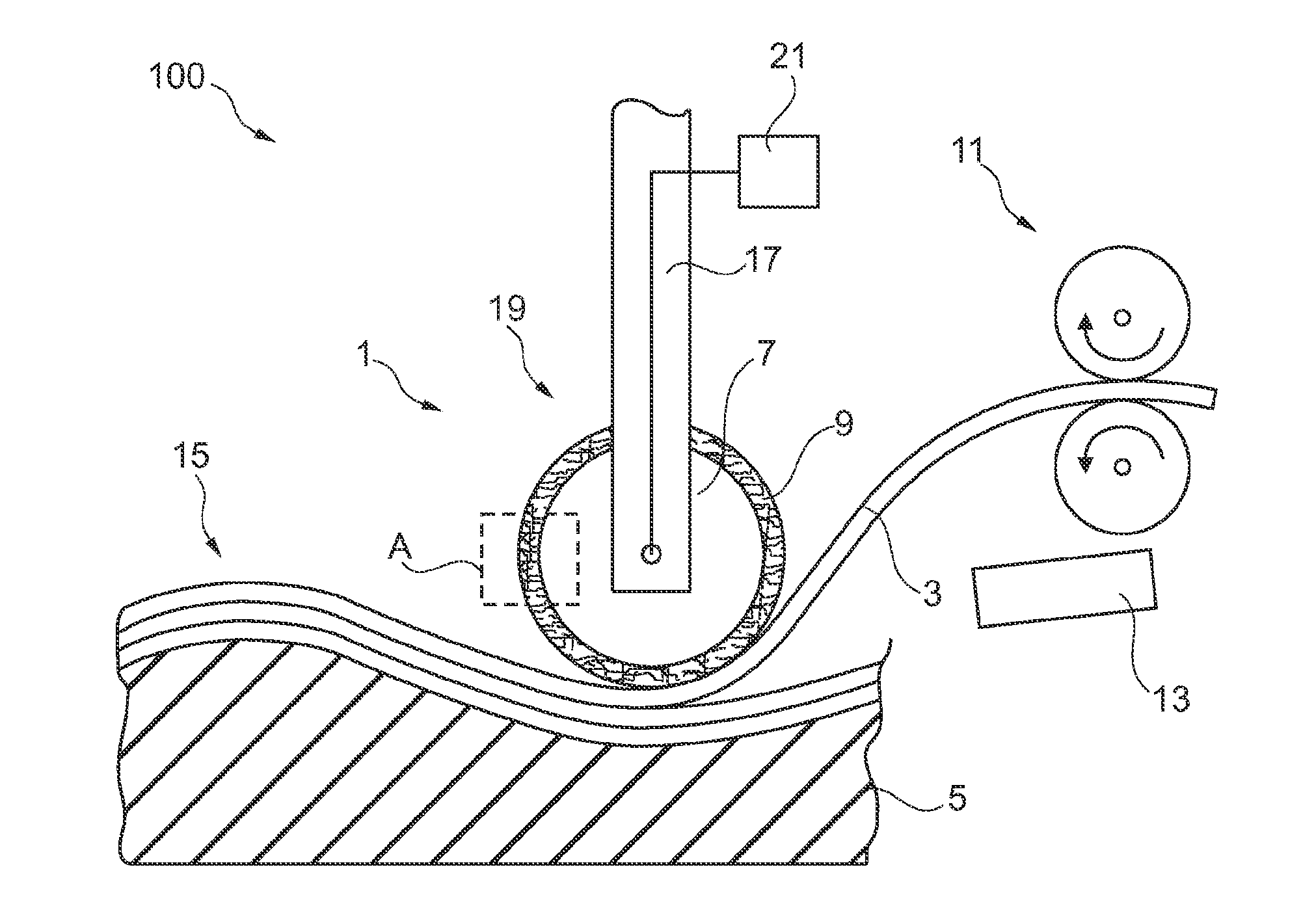
[0024]According to a further embodiment of the invention, the pressing-on device further has a
temperature control unit for the
temperature control of the main body. For example, the main body can be heated with the aid of the
temperature control unit to an elevated temperature in order to further reduce
heat transfer from the hot thermoplastic material to the main body during the pressing on. On the other hand, the main body can be intentionally cooled with the aid of the temperature
control unit, in order to prevent lasting damage to the main body due to the continuous introduction of heat into the main body, e.g., during the pressing on of the hot thermoplastic material. For example, a
water cooler, an air cooler, a Peltier cooler, or similar heating units can be used as the temperature
control unit.
[0032]Because of the uniform pressing on of the thermoplastic material by the advantageously implemented pressing-on device described herein as a result of the flexibility of the pressing-on layer and as a result of the possibly slight
heat transfer from the hot thermoplastic material to the main body and the
slow cooling of the thermoplastic material thus caused during the processing, a very high interlaminar strength of the component formed by the laminate can hereby potentially be achieved.

