
Outdoor cultivator for photosynthetic microorganisms

a technology of photosynthetic microorganisms and cultivators, which is applied in the field of outdoor cultivation systems for photosynthetic microorganisms, can solve the problems of high cost of cosub>2 /sub>sources, low-value biomass products, and inability to achieve low-concentration cosub>2 /sub>sources, etc., and achieve the effect of improving the thermal control of the culture fluid

Inactive Publication Date: 2012-05-10
ELEMENT CLEANTECH
View PDF0 Cites 13 Cited by
  • Summary
  • Abstract
  • Description
  • Claims
  • Application Information

AI Technical Summary

Benefits of technology

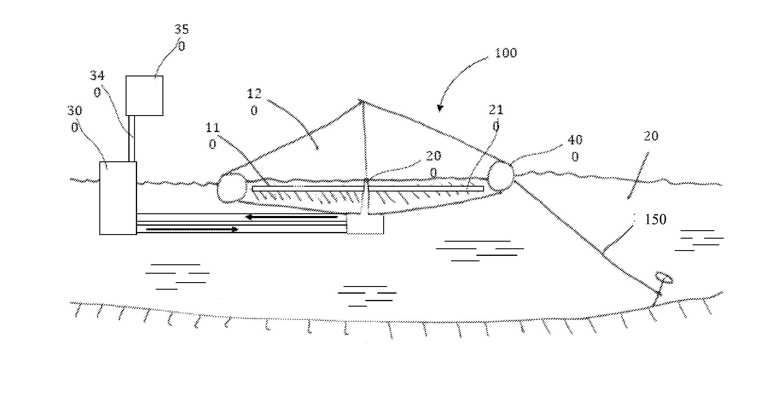
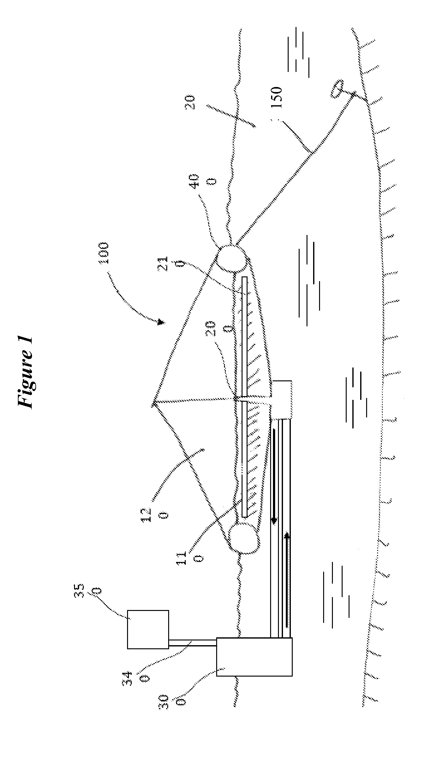
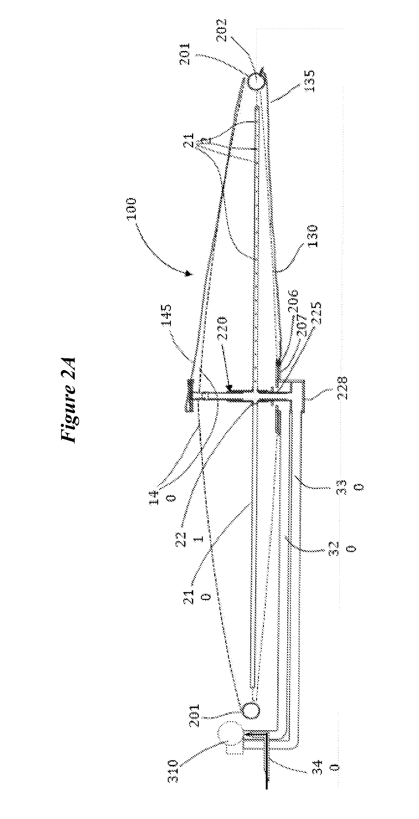
The present invention provides a novel waterborne photosynthetic cultivator that is designed to improve the culture of photosynthetic microorganisms in a large scale and seed scale. The cultivator includes a buoyant frame connected to a top sheet and bottom sheet, which creates a cultivation space with a host pool of water. The water of the host pool is cooled by the circulating pump, which prevents overheating of the culture fluid. The cultivator also includes a simplified and well-integrated mixing system, which promotes turbulent vertical mixing of the photosynthetic microorganisms. The system is enclosed, reducing contamination and evaporative loss. The cultivator can be powered by renewable energy sources and is suitable for photosynthetic micro-organisms like phototrophic algae. The invention provides an efficient and cost-effective solution for large-scale cultivation of photosynthetic microorganisms.

Problems solved by technology

However, since the pond is open, CO2 availability can limit the algal growth, and much of the injected CO2 is lost to the atmosphere.
But making the sump deeper requires increased pumping energy to deliver the gas against the increased hydrostatic head, rendering it impractical for low-concentration CO2 sources and low-value biomass products.
In addition, since raceway ponds systems are often placed in dry sunny regions for high biomass productivity, water loss from the culture due to evaporation from the open culture can be very significant.
The open nature of the system also renders the system vulnerable to contamination by other species of algae, predatory microorganisms, and zooplankton, which constantly threaten the optimal algae biomass productivity in raceway ponds systems and thereby limits commercial culture to a few robust species (see “Commercial production of microalgae: ponds, tanks, tubes and fermenters”, by Borowitzka, Journal of Biotechnology, Volume 70, 1999 (“Borowitzka 1999”); and “Photobioreactors: production systems for phototrophic microorganisms”, by Pulz, Applied Microbiology and Biotechnology, Volume 57, 2004).
Additionally, practical constraints such as providing sufficient thermal mass to maintain desired temperature during the day / night thermal cycle, and providing sufficient depth to guarantee turbulent flow throughout the entire raceway, typically dictate a minimum culture depth in raceways that is greater than would be biologically optimum for common light tolerant species (see “Handbook of Microalgal Culture”, Blackwell Publishing, Richmond ed., 2004).
Therefore, the maximum culture density of raceway is effectively limited, increasing the cost of biomass extraction.
Finally, earth-moving equipment to produce a flat level surface for the masonry construction of the pond requires a significant expense.
Circular ponds require expensive concrete construction, and similarly to the raceway, often inject CO2 at only a single point and rely on the mechanical mixing of a single mixing arm rotating through the pond.
Although a variety of systems have been devised for culturing photosynthetic microorganisms, none has achieved the combination of low cost, ease of operation, robustness, and scalability to allow large-scale cultivation at globally significant scale.

Method used


Image

  • Outdoor cultivator for photosynthetic microorganisms
  • Outdoor cultivator for photosynthetic microorganisms
  • Outdoor cultivator for photosynthetic microorganisms

Examples


example 1

Exemplified Embodiment of Floating Cultivator for Phototrophic Organisms

[0096]FIGS. 8-11 illustrate an embodiment of the floating cultivator floating in an above-ground pool. The cultivator is comprised of a floating ring with a central mast and flexible bottom and top layers. The floating cultivator is depicted as the ring (801), upper canopy (802), lower canopy (not visible in drawing), and central mast (not visible in drawing). Upper pipes (or tubes) are for air supply into (803) and out of (804) the upper canopy. Fresh air is taken in through an inlet air filter (805). The flow of fresh air into the cultivator is facilitated by an inlet blower or fan (806); the flow of oxygen-rich air out of the cultivator is facilitated by an outlet blower or fan (807). Fluid lines (e.g., pipes or tubes) below (808) go to a recirculating pump (809). The air lines and the culture fluid lines may be rigid or flexible depending on what is appropriate for a particular installation and the expected ...


PUM

PropertyMeasurementUnit
depthaaaaaaaaaa
depthaaaaaaaaaa
depthaaaaaaaaaa

Abstract

A novel waterborne cultivator, which provides the benefits of known systems for culture of photosynthetic micro-organisms in a novel configuration, incorporating a simplified, two-phase rotary mixing and gas injection system, the two phases being liquid and gas (CO2). The mixing system provides optimum growth conditions through increased turbulent vertical mixing and increased levels of dissolved CO2 throughout the cultivator via injection of flue gas or other CO2-bearing gas stream. The system thus provides efficient capture and sequestration or reuse of CO2 while producing valuable biomass for food, feed, and fuel use. The waterborne configuration provides further benefits of passive temperature control and automatic leveling for consistent culture depth. Additional benefit is provided by an enclosed design which reduces contamination and evaporative loss by isolating the photosynthetic culture from the outside environment. The simplified and well-integrated design of the cultivator and mixing system greatly reduces capital and operating costs compared to previously known systems.

Description

CROSS-REFERENCE TO RELATED APPLICATIONS[0001]The present application claims the benefit of U.S. Provisional Application No. 61 / 164,446, filed on Mar. 29, 2009 and U.S. Provisional Application No. 61 / 178,441, filed on May 14, 2009, the entire disclosures of both of which are hereby incorporated herein by reference in their entirety.FIELD OF THE INVENTION[0002]The present invention relates to an outdoor cultivation system for photosynthetic microorganisms and more particularly, the present invention relates to a system for cultivating phototrophic microalgae in liquid culture through efficient gas and nutrient injection and distribution, and increasing vertical mixing within the liquid culture.BACKGROUND[0003]Many types of photosynthetic micro-organisms have been cultivated to produce a wide variety of biomass products, ranging from dietary supplements such as omega-3 fatty acids to aquaculture feed. Recently, as a result of heightened interest in CO2 sequestration, attempts have been...

Claims


Application Information

Patent Timeline
Patent Type & Authority Applications(United States)
IPC IPC(8): C12M1/42C12N1/12
CPCC12M21/02C12M23/56C12M41/26C12M29/18C12M29/24C12M27/02
Inventor WINTERS, JARED L.HOBBS, ELLIOT R.WINTERS, JOHN D.V.TOM, ERNESTO A.WRIGHT, CHRISTOPHER
Owner ELEMENT CLEANTECH
Learn More