Method and apparatus for enhanced spatial bandwidth wavefronts reconstructed from digital interferograms or holograms

Inactive Publication Date: 2012-05-10
ECOLE POLYTECHNIQUE FEDERALE DE LAUSANNE (EPFL)
View PDF2 Cites 43 Cited by
  • Summary
  • Abstract
  • Description
  • Claims
  • Application Information

AI Technical Summary

Benefits of technology

[0016]When noise affects the experimental system, only partial suppression of the zero-order may be achieved. It is however possible to fully suppress it by post-processing, such as conventional filtering. In case of critical ex

Problems solved by technology

This method implies that a large part of the spectral bandwidth of the detector is used by terms that carry redundant information, not useful for reconstruction.
This drawback therefore greatly reduces the available bandwidth for the imaging order, and can potentially lead to degradation in its resolution.
Furthermore, when spectral overlap occurs, some artifacts can appear in the images.
The drawback of this method is that the bandwidth available for the imaging orders is greatly decreased by the need to spectrally separate the different terms under conventional sampling conditions.
In general, these methods do not provide perfect reconstruction, since the ope

Method used


Image

  • Method and apparatus for enhanced spatial bandwidth wavefronts reconstructed from digital interferograms or holograms
  • Method and apparatus for enhanced spatial bandwidth wavefronts reconstructed from digital interferograms or holograms
  • Method and apparatus for enhanced spatial bandwidth wavefronts reconstructed from digital interferograms or holograms

Examples


second embodiment

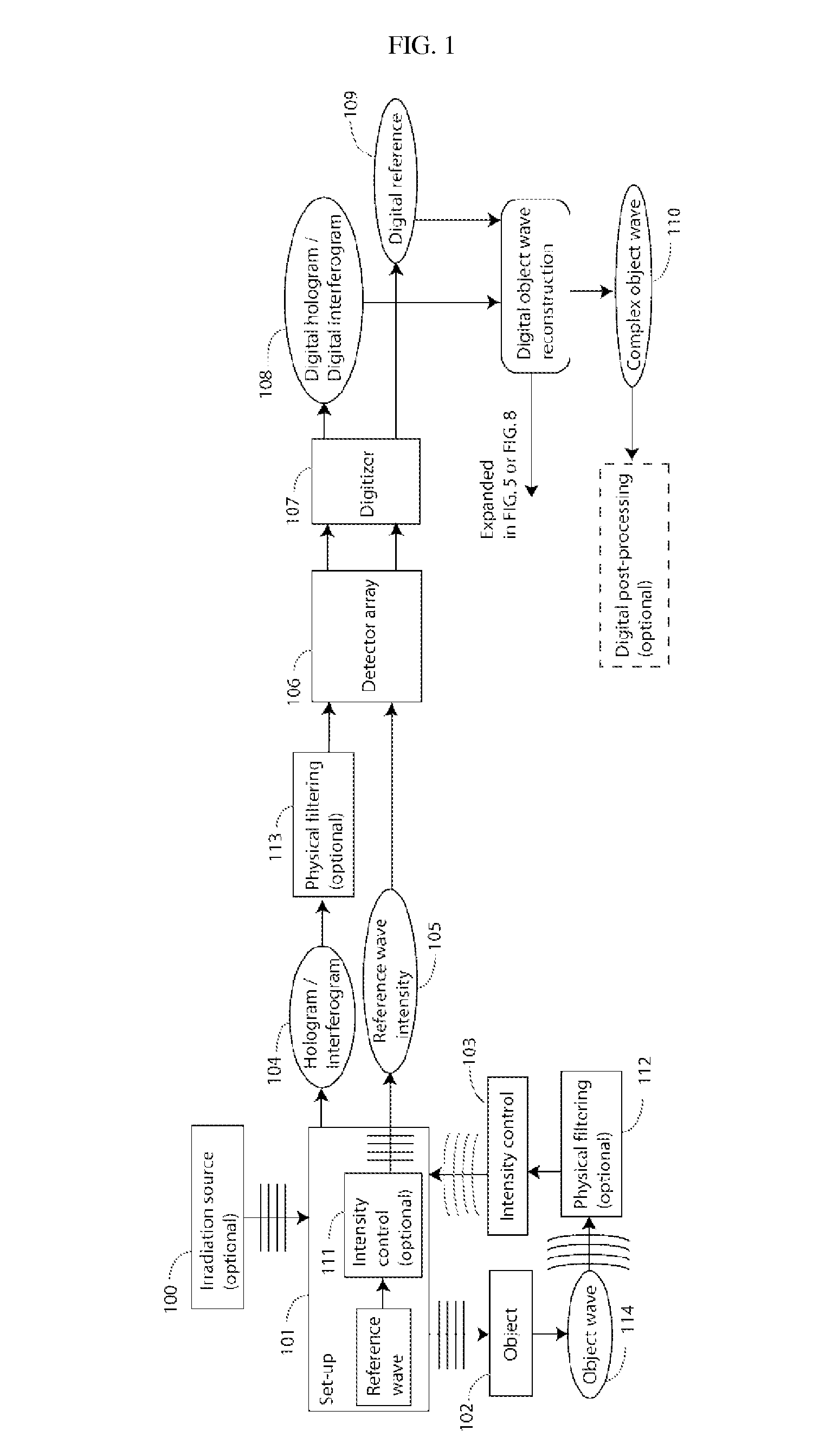
[0041]For the first and second embodiment, the interaction of the source wave with the measured sample can be done in two modes: 1) reflection geometry, where the wave o is reflected by the object, giving information about its shape if it is highly reflective, or its internal structure through back-scattering phenomena if it is mainly transparent within the employed spectral range; 2) transmission geometry, where the wave is diffracted by the sample, giving information about its internal structure.

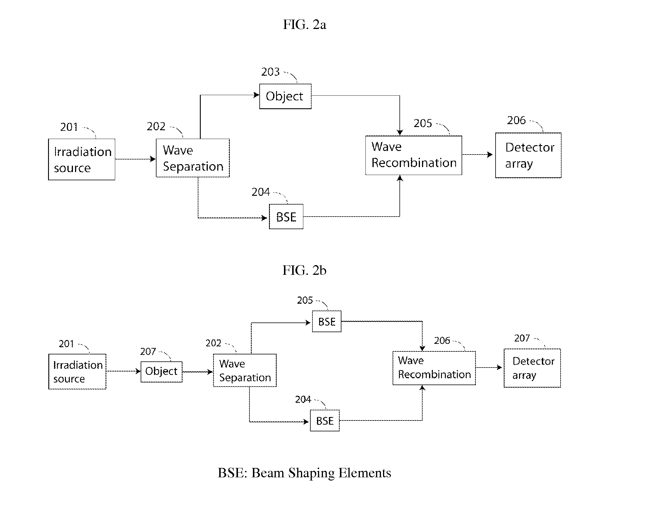
[0042]In a third embodiment, the irradiating source 100 is optional: as for the second embodiment, the wave, said object wave, is conducted to 101 where it creates a hologram 104 by interfering with a reference wave which, in this third embodiment, is also derived from the object wave itself, by using optional beam shaping elements BSE. An independent irradiating source is not necessary and can be considered as confounded with the object: this is the case of optics, if one considers fluore...

third embodiment

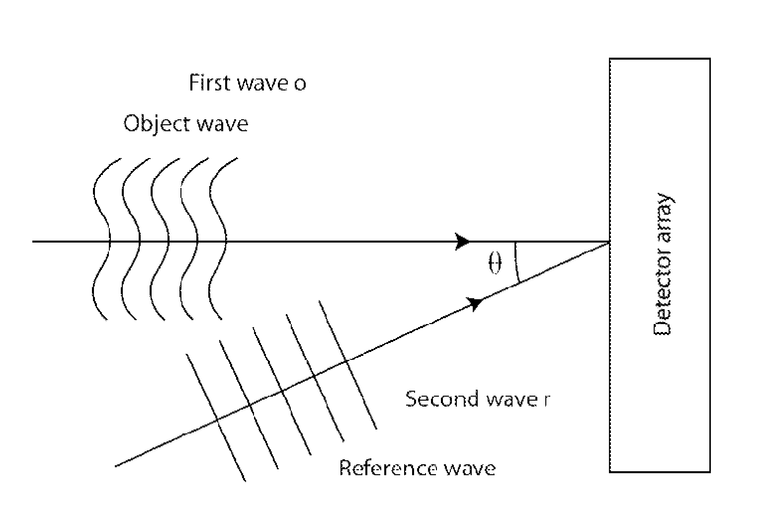
[0045]The coherence requirements are diverse: in microscopy, weak coherence is most often enough. The coherence can be restricted both in the temporal and in the spatial domain. The basic rule is that the extent of the coherence both in the temporal and in the spatial domain must be sufficient to provide a contribution of the mutual coherence terms corresponding to the so called “cross terms” in the development of the interference of the object and reference wave, all over the surface of the detector array. In the third embodiment, where optical emitting molecules, fluorophore or luminophores, are considered, an optical filter, interference filter, filter band-stop, Fabry-Pérot interferometers or etalons can be inserted before the interferogram formation, or before the camera, in order to increase the coherence length.

[0046]The hologram is created by the interference between the said “wave” o (object wave), which interacts with the sample 102 and a second wave r or reference wave ge...


PUM


Abstract

The present invention discloses a method and an apparatus to compute a complex wavefield, referred to as the object wave o, by means of measuring the intensity signal resulting from the interference of the said object wave with a second wave termed the reference wave. The second wave r is assumed to have some non-vanishing mutual coherence with the said object wave o. The reference wave can be obtained from a source or from the object wave itself. The wave may be emitted from sources of variable degree of coherence and can be scattered waves, but also light-emitting molecules, matter waves such as electron beams or acoustical sources. The disclosed method relates to the said “non-linear method” (NLM). The innovation resides in the fact that the NLM improves considerably the bandwidth of the wavefront reconstructed from off-axis interferograms and holograms obtained in a single shot. The advantage is the significant improvement of the resolution of the images obtained from the reconstructed wavefront, i.e. amplitude and phase images. The said method also suppresses the artifacts resulting from the intensity recording of interferograms and holograms. The method is general in the sense that it can be used for any interferometric measurement, provided that it satisfies the simple requirement that the intensity of the reference wave is larger than the intensity of the object wave, and that the object wave modulated by the reference is confined to at least a quadrant of the spectrum. The disclosed method applies to interferometry, holography in optics, electron waves and acoustics. In particular, it can be implemented in phase, fluorescence, luminescence, electron and acoustic microscopy.

Description

FIELD OF THE INVENTION & STATE OF THE ART[0001]The present invention discloses a method and an apparatus to compute the complex object wavefield o by means of measuring the intensity signal resulting from the interference of the said wave o with a second wave r, this second wave having some non-vanishing mutual coherence with the said object wave. In its most general implementation, the apparatus comprises a device generating a wave, which will be analyzed by the measurement of the intensity of the wave resulting from the interference of the said “wave” o with the said “second wave” r. This description of the invention includes in particular holography, which describes a method of reconstructing complex-wave from a hologram formed by the interference of an object wave o and a reference wave r considered as the second wave. The basic approach of holography assumes that the object wave o originates from the scattering of a wave from an irradiating source and that the reference wave r ...

Claims


Application Information

Patent Timeline
IPC IPC(8): G06F19/00
CPCG03H1/0866G03H2001/0825G03H2001/0456
Inventor PAVILLON, NICOLASSEELAMANTULA, CHANDRA SEKHARUNSER, MICHAELDEPEURSINGE, CHRISTIAN
Owner ECOLE POLYTECHNIQUE FEDERALE DE LAUSANNE (EPFL)
Why Eureka
Try Eureka