Stents and methods of making stents

a technology of stents and stents, which is applied in the direction of prosthesis, blood vessels, catheters, etc., can solve the problems of increased risk of late thrombosis, renarrowing of blood vessels, and occlusion or weakened passageways, so as to reduce materials waste, reduce manufacturing steps, and reduce manufacturing costs

Inactive Publication Date: 2012-06-14
MICROPEN TECH CORP
View PDF5 Cites 58 Cited by
  • Summary
  • Abstract
  • Description
  • Claims
  • Application Information

AI Technical Summary

Benefits of technology

[0015]One of the advantages of this invention is the potential to lower manufacturing cost by reducing materials waste and removing manufacturing steps. In addition, the present invention enables greater design flexibility and customization compared with current practices in manufacturing of stents. The methods described in the present invention allow flexibility in the design of strut geometries as well as provide the ability to precisely fine tune strut compositions of stents by altering chemical or physical properties of the inks.

Problems solved by technology

These passageways can become occluded or weakened with time or disease.
Bare metal stents, formed of materials such as stainless steel or shape memory alloys, were originally used, but suffer from inflammatory responses leading to renarrowing of the blood vessel.
However, such drug-eluting stents increase the risk of late thrombosis, thought to be caused by the body's long term reaction to the polymeric material bearing the drug.
Some concerns with this process include sharp edges or burrs, and in the case of polymers, overheating and consequent unintended changes in the microstructure.
All such methods suffer from substantial material waste.
Such assembly processes may prove tedious and are particularly difficult if bioresorbable filaments of a particular composition are not readily available, or if particular additives must be included (e.g. for radiopacity, drug delivery or mechanical property alteration) but prove difficult to spin into fiber form.
Such alternatives offer relatively poor control of perforation size, shape, and uniformity.
In addition, there is a limited selection of materials which can be successfully processed in this fashion.

Method used


Image

  • Stents and methods of making stents
  • Stents and methods of making stents
  • Stents and methods of making stents

Examples


example 1

Polycaprolactone Stent

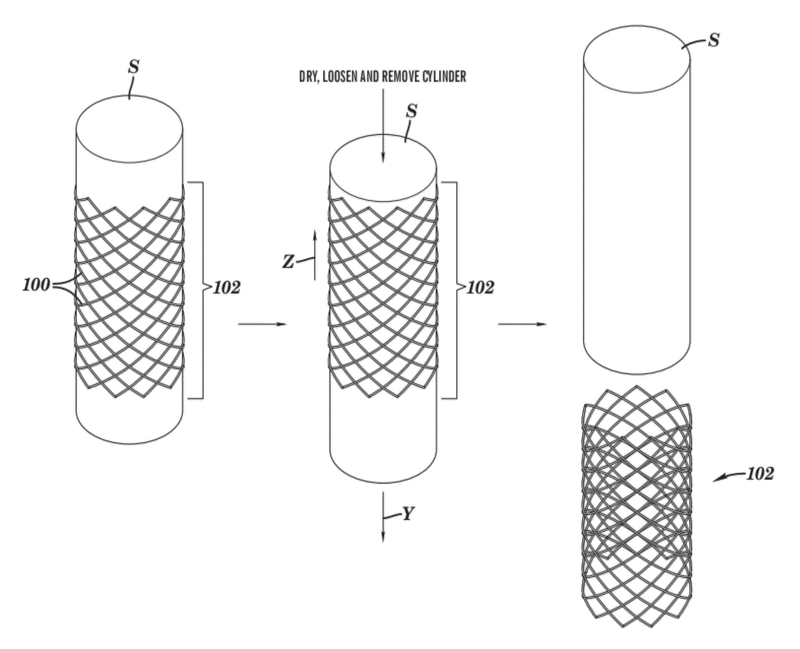
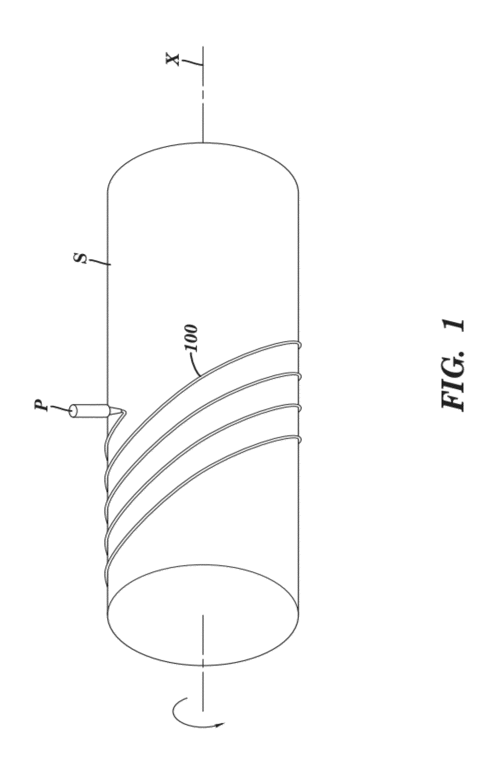
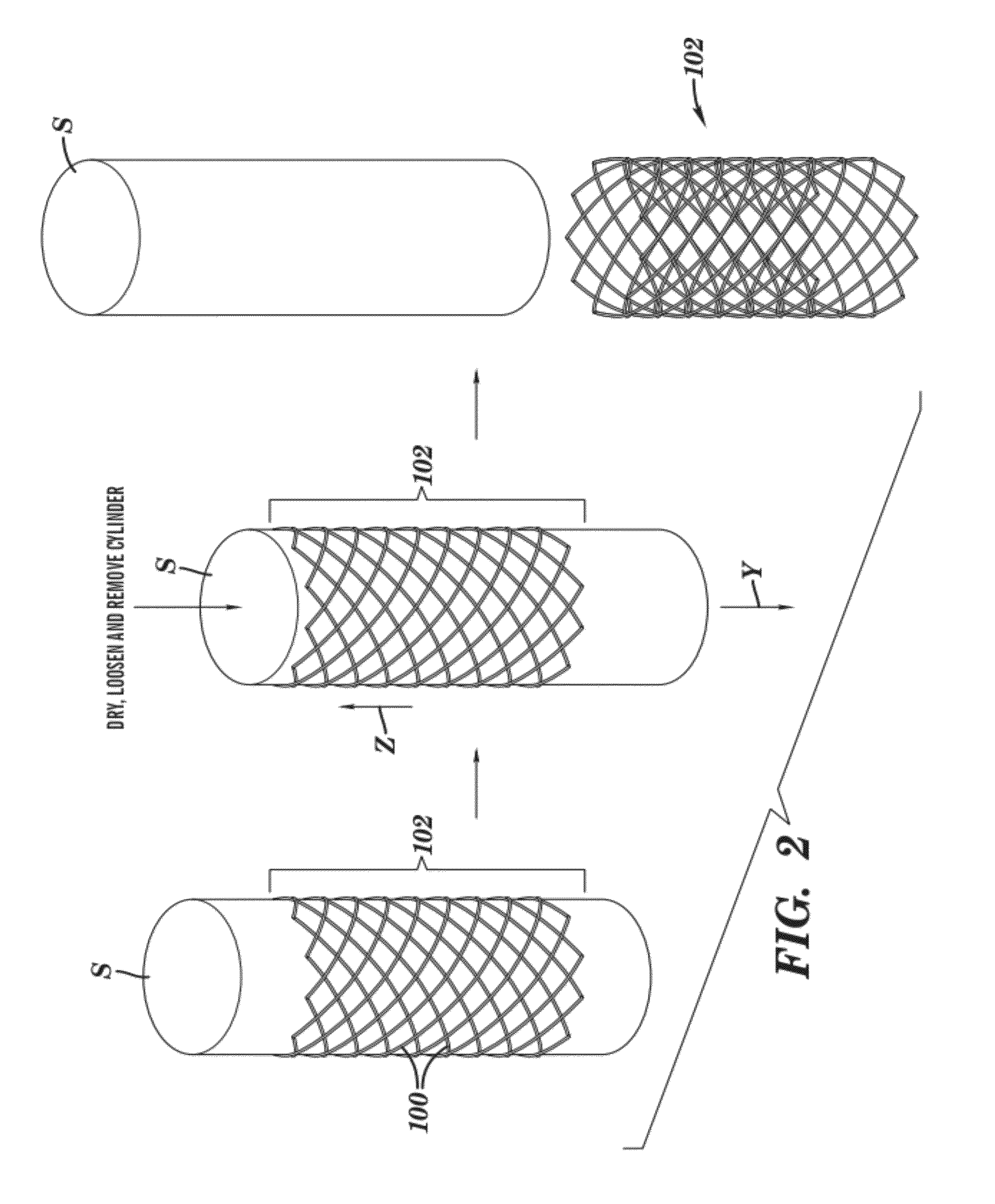
[0070]Polycaprolactone (Mn 70,000-90,000; Sigma-Aldrich) was dissolved in tetrahydrofuran (Sigma-Aldrich) at a level of 20% by weight. This stent ink was deposited by a Micropen™ writing device in a continuous open pattern on a polytetrafluoroethylene (PTFE) tube (5 cm outer diameter; Zeus Advanced Biomaterials). A total of four layers were applied, each one positioned directly on top of the previous one. After the first, second, and third layers were applied, the stent was allowed to dry under ambient conditions for approximately 5 minutes before writing the next layer. After the fourth layer was printed, the stent was cured at 55° C. for 10 minutes in a forced air oven. The stent was easily removed in a single piece from the PTFE tube, yielding a device with a thickness of approximately 80 μm and a strut width approximately 0.7 mm. The openings between struts were approximately 1.5 mm in width and 3 mm in length. The entire stent length was approximately 20 m...

example 2

Radiopaque Polycaprolactone Stent

[0071]To the polycaprolactone ink described in Example 1, tungsten powder (99.9%, 1-5 μm, Alfa-Aesar) was added to yield a weight ratio of tungsten:polycaprolactone of 88:12 (volume ratio of 30:70) and a total solids level of 67.6% by weight. A radiopaque stent was produced by writing a single layer of this ink, using a Micropen™ writing device, on a polytetrafluoroethylene (PTFE) tube (3.6 cm outer diameter; Zeus Advanced Biomaterials) and drying at 55° C. for 10 minutes before removing from the PTFE tube. The thickness of the resulting stent was 36 μm, and the length and opening dimensions were identical to that described in Example 1.

example 3

Two-Part Stent that is Radiopaque Only at its Ends

[0072]Example 1 was repeated except only two layers of ink were deposited, resulting in a stent approximately 40 mm thick. Subsequently, the tungsten filled ink of Example 2 was deposited only over the struts on either end of the stent. This final product was cured at 55° C. for 10 minutes and removed from the tube.


PUM


Abstract

The present invention relates to a stent having a longitudinally-extending passage defined by a plurality of seamless strut elements with spacing between them. Each of these strut elements are in the form of lines defining the passage. The strut elements have a thickness in the range of 30 microns to 150 microns and are formed as at least one written layer. Also disclosed are methods of making the stent.

Description

[0001]This application claims the benefit of U.S. Provisional Patent Application Ser. No. 61 / 421,951, filed Dec. 10, 2010, which is hereby incorporated by reference in its entirety.FIELD OF THE INVENTION[0002]The present invention relates to stents and methods of making the stents.BACKGROUND OF THE INVENTION[0003]Stents may be used to treat stenosis, strictures, or coarctations which are abnormal narrowings in blood vessels, tracts, or other tubular organs or structures in the body. They are most commonly used to treat coronary artery stenosis.[0004]There are various longitudinally-extending passageways in an animal body, which include, for example, blood vessels and other body lumens. These passageways can become occluded or weakened with time or disease. For example, they can be occluded by a tumor, restricted by plaque, or weakened by an aneurysm. When this occurs, the passageway can be reopened or reinforced, or even replaced, with a stent. A stent is an artificial implant that ...

Claims


Application Information

Patent Timeline
Patent Type & Authority Applications(United States)
IPC IPC(8): A61F2/82A61K9/70
CPCA61F2/88A61F2250/003A61F2250/0067A61F2240/001
Inventor SHAW-KLEIN, LORI J.
Owner MICROPEN TECH CORP
Why Eureka
Try Eureka