Composite crucible and method of manufacturing the same

a technology of composite crucible and manufacturing method, which is applied in the direction of manufacturing tools, crystal growth process, polycrystalline material growth, etc., can solve the problems of toxic barium handling, time and effort required for coating, and insufficient high temperature strength, and achieve low cost and high strength.

Active Publication Date: 2012-06-28
SUMCO CORP
View PDF3 Cites 9 Cited by
  • Summary
  • Abstract
  • Description
  • Claims
  • Application Information

AI Technical Summary

Benefits of technology

[0029]Thus, according to the present invention, there is provided a crucible which has high strength at high temperature, can be used for a long time, and can be manufactured at low cost, and there is also provided a method of manufacturing the crucible.

Problems solved by technology

The conventional crucible having the layer containing aluminium (Al) in high concentration has relatively high viscosity, but the high temperature strength is not sufficient.
Furthermore, the crucible obtained by coating barium, as a crystallization promoter, onto a surface can be strengthen by the crystallization of the crucible surface, but the coating requires time and effort, and the handling of the toxic barium is problematic.
When a vitreous silica crucible is used for a long time, inward sagging of the sidewall of the crucible can occur.
When a vitreous silica layer is provided on the inner surface, the difference in the thermal expansion coefficient between mullite and vitreous silica can cause formation of cracks in the crucible during heating the crucible.
However, when the reinforcement layer is formed only on the rim upper end portion, no cracks are formed in the crucible, and thus long-time use is made possible.

Method used


Image

  • Composite crucible and method of manufacturing the same
  • Composite crucible and method of manufacturing the same
  • Composite crucible and method of manufacturing the same

Examples


example

Example 1

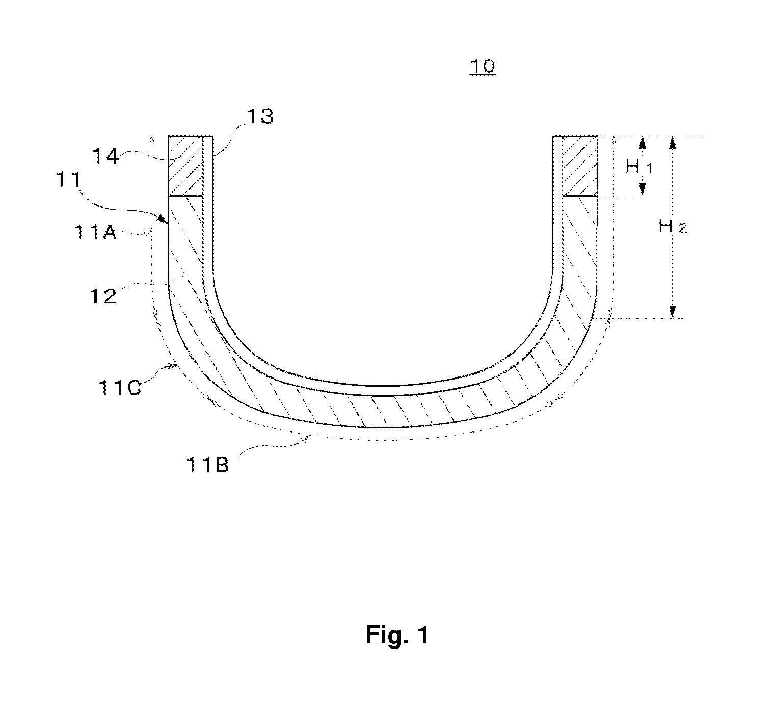
[0077]Sample A1 of the composite crucible was prepared. The crucible had a diameter of 16 inches (opening diameter of about 400 mm), a height of the 250 mm. The wall thickness of the crucible was 6.5 mm at the straight body portion, 8 mm at the corner portion, and 5 mm at the bottom portion. The thicknesses of the transparent vitreous silica layer and the opaque vitreous silica layer at the sidewall portion were 0.5 mm and 6 mm, respectively. Furthermore, a mullite reinforcement layer was provided on the upper end portion of the crucible. The height H2 of the sidewall portion was 150 mm and the height H1 of the reinforcement layer was about 15 mm (H1=0.1 H2).

[0078]Next, Crucible Sample A1 was heated for a long time in a furnace, and the deformation state of the crucible was observed. The heating conditions were as follows. First the temperature was increased at a constant rate from the room temperature to about 1580 deg. C. over 5 hours, and the temperature was maintained a...

example 2

[0081]Crucible Sample A2 having the same structure except that the height H1 of the reinforcement layer was about 50 mm (H1≈0.33 H2) was prepared and subjected to the same heating test as in Example 1. As shown in Table 1, deformation such as inward sagging and buckling was not visually observed, and there was no crack on the sidewall portion.

example 3

[0082]Crucible Sample A3 having the same structure except that the height H1 of the reinforcement layer was about 75 mm (H1=0.5 H2) was prepared and subjected to the same heating test as in Example 1. As shown in Table 1, deformation such as inward sagging and buckling was not visually observed, and there was no crack on the sidewall portion.


PUM

PropertyMeasurementUnit
thicknessaaaaaaaaaa
thicknessaaaaaaaaaa
thicknessaaaaaaaaaa

Abstract

The purpose of the present invention is to provide a crucible which has high viscosity at high temperature, can be used for a long time, and can be manufactured at low cost, and a method of manufacturing the crucible. The present invention provides a composite crucible including a vitreous silica crucible body having a sidewall portion and a bottom portion, and a reinforcement layer provided on an outer surface side of an upper end portion of the vitreous silica crucible body, wherein the reinforcement layer is made of mullite material whose main component is alumina and silica.

Description

CROSS-REFERENCE TO RELATED APPLICATION[0001]This application is related to Japanese Patent Application No. 2010-293567 filed on Dec. 28, 2010, whose priority is claimed and the disclosure of which is incorporated by reference in its entirety.BACKGROUND OF THE INVENTION[0002]1. Field of the Invention[0003]The present invention relates to a composite crucible used for manufacturing a silicon crystal, and a method of manufacturing the crucible.[0004]2. Description of the Related Art[0005]Nowadays, the demand for a solar cell has been increasing in consideration of environment problem and energy problem. The solar cell is generally classified into a silicon solar cell and a compound semiconductor solar cell, based on the kind of the semiconductor used for the power generation part. Furthermore, the silicon solar cell is classified into a crystalline silicon solar cell and an amorphous silicon solar cell. The crystalline silicon solar cell is classified into a monocrystalline silicon sol...

Claims


Application Information

Patent Timeline
Patent Type & Authority Applications(United States)
IPC IPC(8): C30B35/00C03B19/09
CPCC03B19/095C30B15/10Y10T117/10C30B35/002C30B29/06Y02E10/50Y02P40/57C03B20/00H01L31/04
Inventor SUDO, TOSHIAKIKITAHARA, KENYOSHIOKA, TAKUMA
Owner SUMCO CORP
Why Eureka
Try Eureka