Permanent magnet and manufacturing method thereof

a permanent magnet and manufacturing method technology, applied in the field of permanent magnets, can solve the problems of poor heat resistance, inability to achieve very fine crystal grain size, so as to achieve the effect of reducing residual magnetic flux density, avoiding serious deformation of magnetic properties, and improving magnetic properties

Inactive Publication Date: 2012-07-19
NITTO DENKO CORP
View PDF11 Cites 14 Cited by
  • Summary
  • Abstract
  • Description
  • Claims
  • Application Information

AI Technical Summary

Benefits of technology

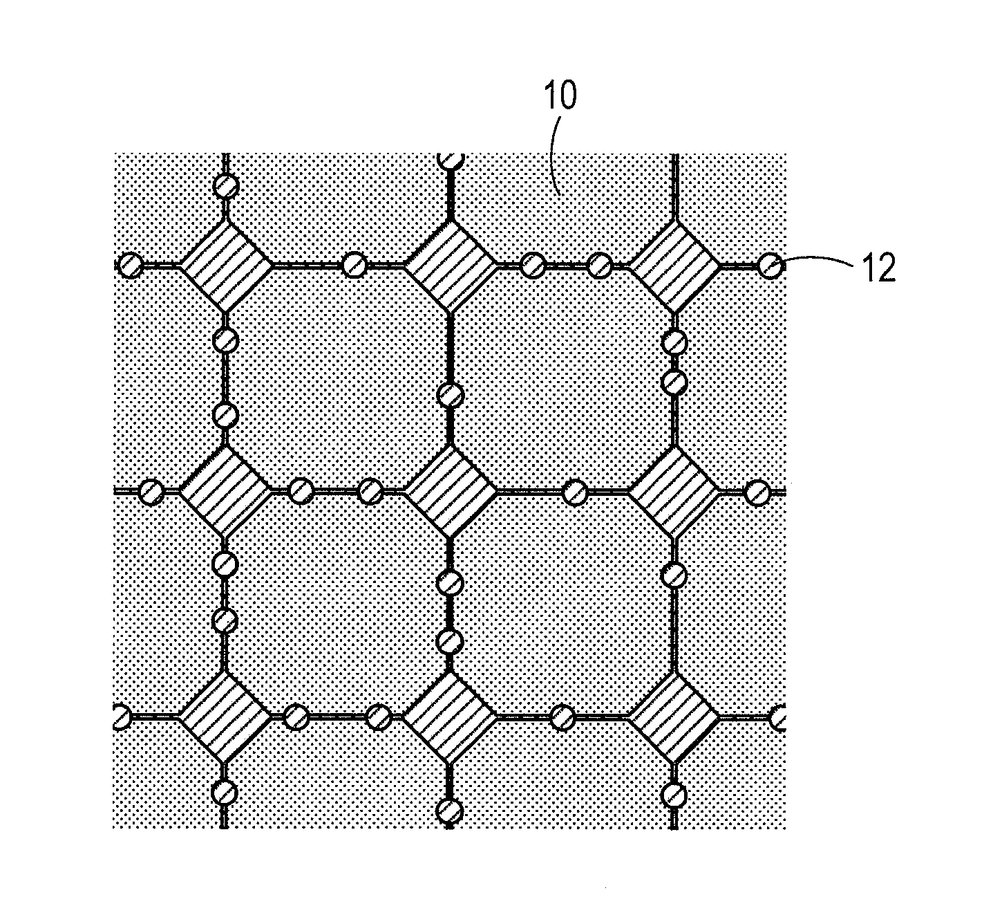
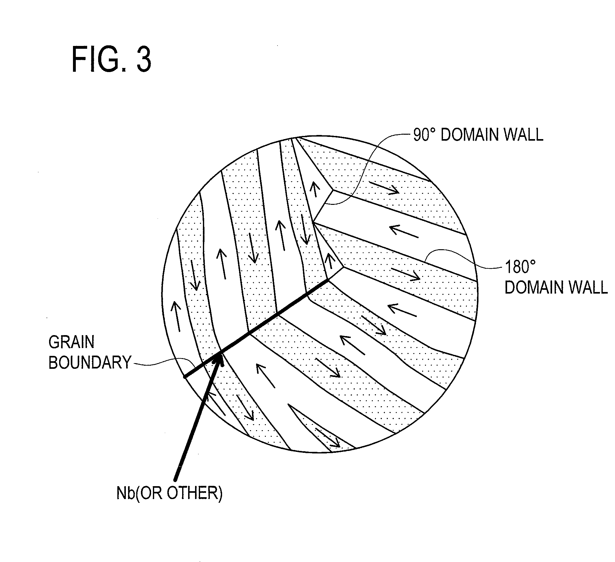
[0028]According to the permanent magnet of the present invention, V, Mo, Zr, Ta, Ti, W, or Nb contained in the organometallic compound can be efficiently concentrated in grain boundaries of the magnet. As a result, the grain growth in the magnet particles during sintering can be inhibited, and at the same time, magnetization reversal of each crystal grain is prevented through disrupting exchange interaction among the crystal grains, enabling magnetic properties to be improved. Furthermore, as the additive amount of V, Mo, Zr, Ta, Ti, W, or Nb can be made smaller than that in a conventional method, the residual magnetic flux density can be inhibited from lowering. Furthermore, since the magnet powder to which the organometallic compound is added is calcined by plasma heating prior to sintering, oxygen content contained in magnet particles can be reduced before sintering of the magnet. Consequently, since such mannered manufacturing process can prevent alpha iron from separating out in a main phase of the sintered magnet and also prevent formation of oxides, serious degrade in the magnetic properties can be avoided.
[0029]Furthermore, the calcination process is performed to the powdered magnet particles, which is advantageous in that the reduction of metal oxides can be performed more easily to the whole magnet particles, compared with a case where the magnet particles are calcined after compaction. That is, the oxygen content in the powdered magnet particles can be more reliably decreased.
[0030]According to the permanent magnet of the present invention, V, Mo, Zr, Ta, Ti, W, or Nb contained in the organometallic compound can be efficiently concentrated in grain boundaries of the magnet. As a result, the grain growth in the magnet particles during sintering can be inhibited, and at the same time, magnetization reversal of each crystal grain is prevented through disrupting exchange interaction among the crystal grains, enabling magnetic properties to be improved. Furthermore, as the additive amount of V, Mo, Zr, Ta, Ti, W, or Nb can be made smaller than that in a conventional method, the residual magnetic flux density can be inhibited from lowering. Furthermore, since the compact body consisting of the organometallic-compound-added magnet powder is calcined by plasma heating prior to sintering, oxygen content contained in magnet particles can be reduced before sintering of the magnet. Consequently, since such mannered manufacturing process can prevent alpha iron from separating out in a main phase of the sintered magnet and also prevent formation of oxides, serious degrade in the magnetic properties can be avoided.
[0031]According to the permanent magnet of the present invention, since the high temperature hydrogen plasma heating is applied as specific means for calcination, high concentration of hydrogen radicals can be generated. Accordingly, even if the metal forming an organometallic compound is present in the magnet powder in a state of a stable oxide, the reduction to a metal or lowering of the oxidation number thereof can be easily performed at a low temperature using the hydrogen radicals.
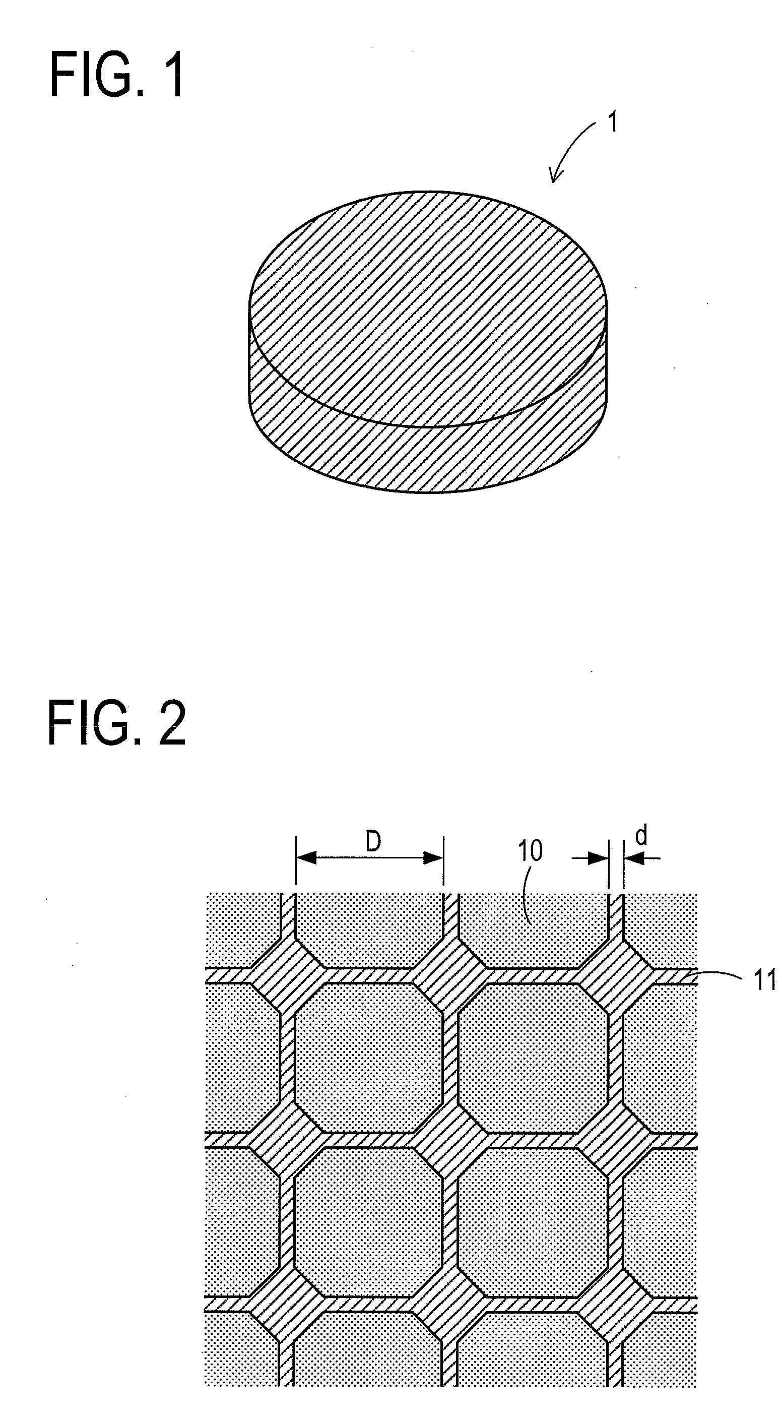
[0032]According to the permanent magnet of the present invention, grain growth during sintering can be prohibited with respect to magnet particles having single domain particle size. Furthermore, through inhibiting the grain growth, the crystal grain of the sintered permanent magnet can be made to have a single domain structure. As a result, the magnetic property of the permanent magnet can be drastically improved.
[0033]According to the permanent magnet of the present invention, the organometallic compound composed of alkyl group is used as organometallic compound to be added to the magnet powder. Therefore, thermal decomposition of the organometallic compound can be caused easily. Consequently, in a case where magnet powder or a compact body is calcined in hydrogen prior to sintering, for instance, carbon content in the magnet powder or the compact body can be reduced more reliably. Accordingly, such mannered manufacturing process can prevent alpha iron from separating out within a main phase of the sintered magnet. Thereby, the whole magnet can be densely sintered and the lowering of the coercive force can be prevented.

Problems solved by technology

On the other hand, as to Nd-based magnets such as Nd—Fe—B magnets, poor heat resistance is pointed to as defect.
However, even if the magnet raw material finely milled into a very fine particle size is compacted and sintered, grain growth occurs in the magnet particles at the time of sintering.
Therefore, after sintering, the crystal grain size in the sintered body increases to be larger than the size before sintering, and as a result, it has been impossible to achieve a very fine crystal grain size.
In addition, if the crystal grain has a larger size, the domain walls created in a grain easily move, resulting in drastic decrease of the coercive force.

Method used


Image

  • Permanent magnet and manufacturing method thereof
  • Permanent magnet and manufacturing method thereof
  • Permanent magnet and manufacturing method thereof

Examples


embodiment

[0097]In comparison with fraction regarding alloy composition of a neodymium magnet according to the stoichiometric composition (Nd: 26.7 wt %, Fe (electrolytic iron): 72.3 wt %, B: 1.0 wt %), proportion of Nd in that of the neodymium magnet powder for the embodiment 1 is set higher, such as Nd / Fe / B=32.7 / 65.96 / 1.34 in wt %, for instance. Further, 5 wt % of niobium n-propoxide has been added as organometallic compound to milled neodymium magnet powder. A calcination process with plasma heating has been performed by using high temperature hydrogen plasma. Regarding flow rate of gases to be supplied during the calcination process, both hydrogen feed rate and Argon feed rate are set to 3 L / min. The output voltage at plasma excitation is set to 3 kW, and the plasma-irradiation is performed for 60 seconds. Sintering of the compacted-state calcined body has been performed in the SPS. Other processes are the same as the processes in [First Method for Manufacturing Permanent Magnet] mentione...


PUM

PropertyMeasurementUnit
thicknessaaaaaaaaaa
thicknessaaaaaaaaaa
grain sizeaaaaaaaaaa

Abstract

There are provided a permanent magnet and a manufacturing method thereof capable of inhibiting grain growth of magnet grains having single domain particle size during sintering so as to improve magnetic properties. To fine powder of milled neodymium magnet is added an organometallic compound solution containing an organometallic compound expressed with a structural formula of M-(OR)x (M represents V, Mo, Zr, Ta, Ti, W or Nb, R represents a substituent group consisting of a straight-chain or branched-chain hydrocarbon, x represents an arbitrary integer) so as to uniformly adhere the organometallic compound to particle surfaces of the neodymium magnet powder. Thereafter, the desiccated magnet powder is calcined by utilizing plasma heating and the powdery calcined body is sintered so as to form a permanent magnet 1.

Description

TECHNICAL FIELD[0001]The present invention relates to a permanent magnet and manufacturing method thereof.BACKGROUND ART[0002]In recent years, a decrease in size and weight, an increase in power output and an increase in efficiency have been required in a permanent magnet motor used in a hybrid car, a hard disk drive, or the like. To realize such a decrease in size and weight, an increase in power output and an increase in efficiency in the permanent magnet motor mentioned above, film-thinning and a further improvement in magnetic performance are required of a permanent magnet to be buried in the permanent magnet motor. Meanwhile, as permanent magnet, there have been known ferrite magnets, Sm—Co-based magnets, Nd—Fe—B-based magnets, Sm2Fe17Nx-based magnets or the like. As permanent magnet for permanent magnet motor, there are typically used Nd—Fe—B-based magnets due to remarkably high residual magnetic flux density.[0003]As method for manufacturing a permanent magnet, a powder sinte...

Claims


Application Information

Patent Timeline
Patent Type & Authority Applications(United States)
IPC IPC(8): H01F7/02B22F1/00B22F3/12H01F41/02
CPCC22C33/02C22C2202/02H01F41/0266H01F1/0577H01F1/086H01F1/0572H01F41/02H01F1/08B22F1/16
Inventor OZEKI, IZUMIKUME, KATSUYAHIRANO, KEISUKEOMURE, TOMOHIROTAIHAKU, KEISUKEOZAKI, TAKASHI
Owner NITTO DENKO CORP
Why Eureka
Try Eureka