Implant device for stimulating osteogenesis and osseointegration
a technology of osseointegration and implant, which is applied in the field of implant devices, can solve the problems of reducing bone mass and density, and affecting the osseointegration process, so as to improve bone quality, shorten the osseointegration time of the implant, and reduce the healing time
- Summary
- Abstract
- Description
- Claims
- Application Information
AI Technical Summary
Benefits of technology
Problems solved by technology
Method used
Image
Examples
example 1
Magnetic Flux Density Distribution
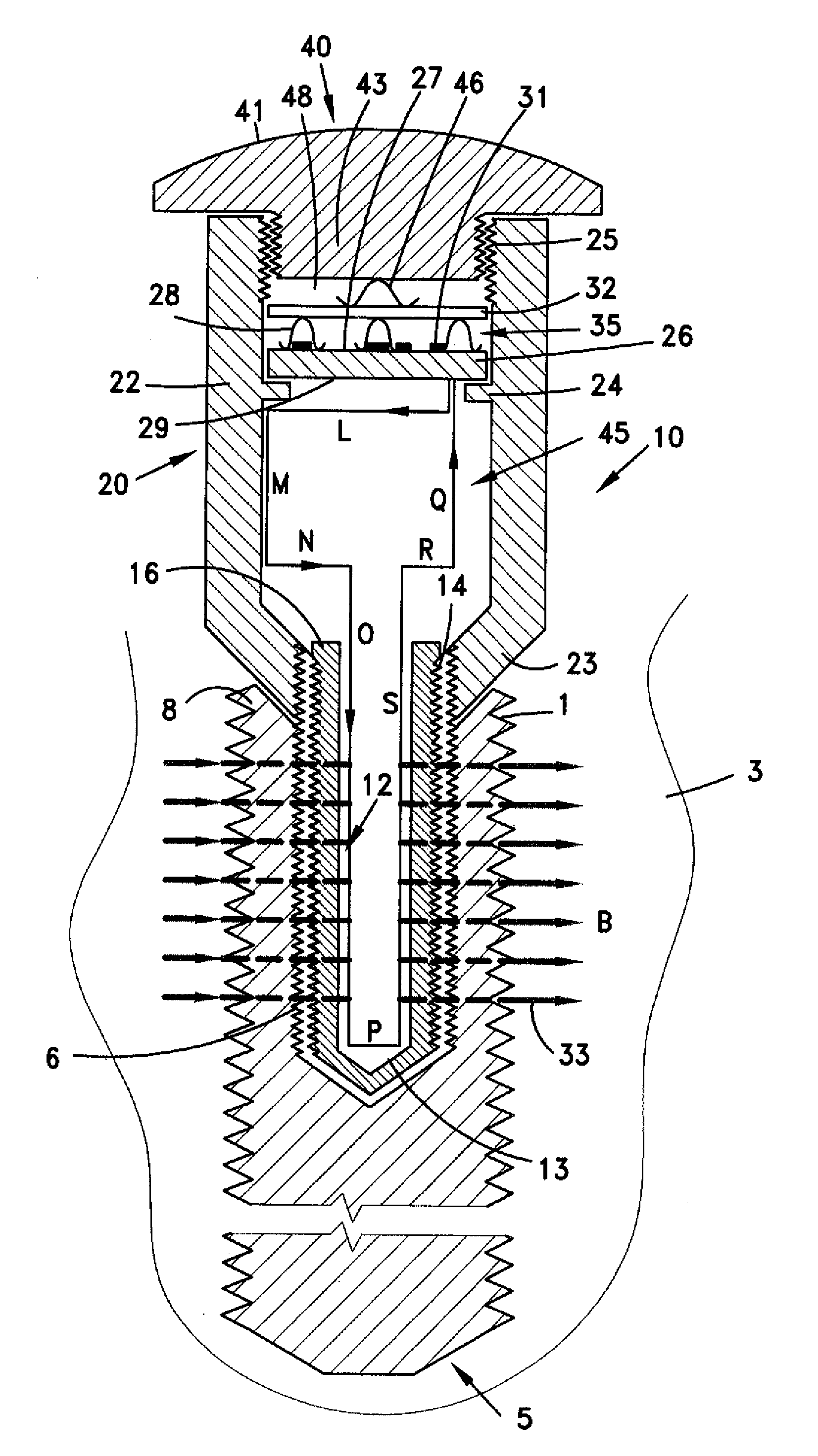
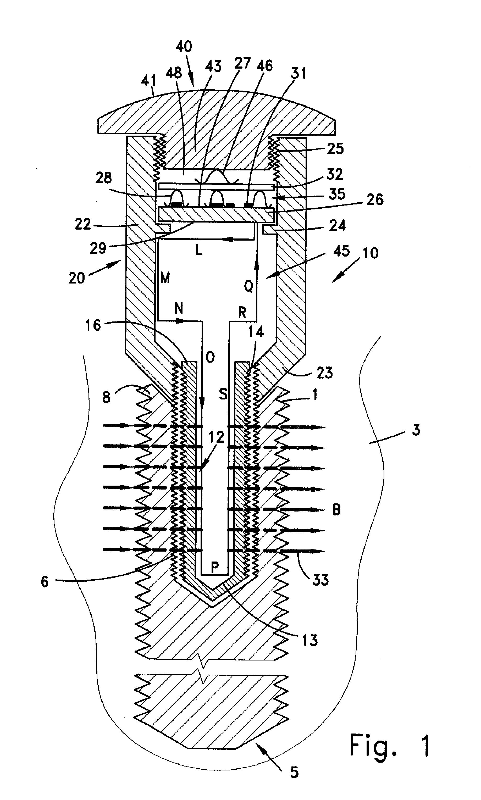
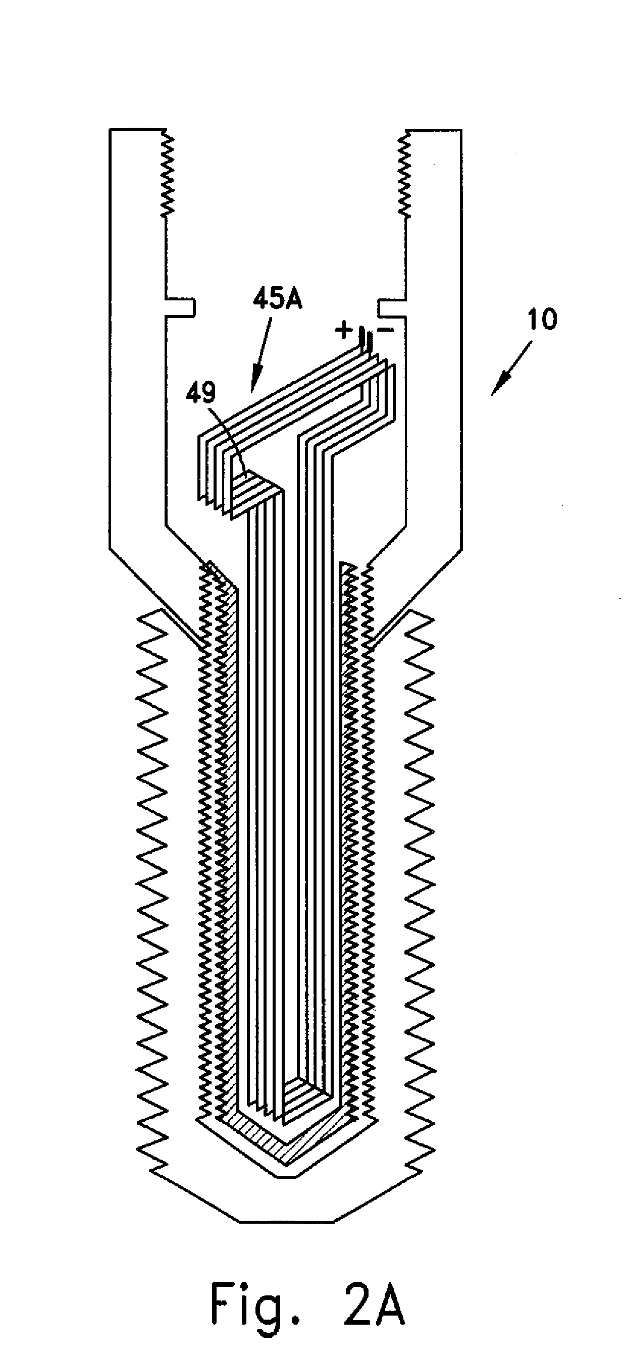
[0127]FIG. 11 is a simulation of the magnetic flux that is generated by means of two mutually perpendicular frame coils similar to those illustrated in FIG. 3 although with only winding and of an extension coil mounted within an implant. The coil is disposed within the open void of the implant, up to a height of 7 mm from the apical end of the implant device. The magnetic flux density distribution is shown as a function of the cervical distance from the apical end of the implant device, as indicated in Table I.
TABLE IHeight [mm]12108642Maximal0.560.580.520.170.040.017magneticfluxdensity[mT]
example 2
[0128]Magnetic Flux Density Distribution with Ferrite Core
[0129]The magnetic flux density distribution for the coil assembly of FIG. 15 was simulated based on two mutually perpendicular frame coils, each of which having a height of 5 mm and a width of 5 mm and a wire diameter of 0.4 mm. The apical edge of the frame coil was selected to be separated 13 mm from the apical end of the implant device, and the coronal edge of the frame coil was selected to be separated 18 mm from the apical end of the implant device.
[0130]The cylindrical ferrite core associated with the cap was selected to have a diameter of 4.5 mm and a height of 3.1 mm. The apical edge of the cylindrical ferrite core was selected to be separated 13.3 mm from the apical end of the implant device, and its coronal edge was selected to be separated 16.4 mm from the apical end of the implant device. The elliptical ferrite core associated with the hollow screw was selected to have a major axis of 1.3 mm, a minor axis of 0.8 m...
example 3
Skin Effect
[0132]Prior to determining the magnetic field attenuation of an exemplary tube provided with an internal magnetic field source, having a relatively large ratio of axial length to radial length, and made of titanium alloy, the attenuation at a portion thereof which is internal to the tube outer edge (hereinafter the “skin”) is first evaluated.
[0133]The decrease in current density from the inner to outer surface of the tube is given by the following equation:
J(d)=Js exp(−d / δ), Equation (1)
[0134]where J is the current density, Js is the current density at the inner surface, d is a given thickness within the tube from its inner surface, and δ is given by the following expression:
δ=ρπfμ,Equation(2)
[0135]where ρ is the tube resistivity, μ is the tube magnetic permeability, and f is the magnetic field frequency.
[0136]For the titanium alloy used for implants, ρ=1.75 10̂(−6) Ωm and μ=1.00005*4π 10̂(−7) N / A. Thus for a frequency of f=1 kHz, δ=21 mm, while for a frequency of f=1 M...
PUM
 Abstract
Description
Claims
Application Information
 - R&D
- Intellectual Property
- Life Sciences
- Materials
- Tech Scout
- Unparalleled Data Quality
- Higher Quality Content
- 60% Fewer Hallucinations
Browse by: Latest US Patents, China's latest patents, Technical Efficacy Thesaurus, Application Domain, Technology Topic, Popular Technical Reports.
© 2025 PatSnap. All rights reserved.Legal|Privacy policy|Modern Slavery Act Transparency Statement|Sitemap|About US| Contact US: help@patsnap.com


