Dispersed Bubble Reactor For Enhanced Gas-Liquid-Solids Contact And Mass Transfer

a gas-liquid solids and reactor technology, applied in the direction of separation processes, products, chemical/physical/physicochemical processes, etc., can solve the problems of not being able to achieve at least 90% cosub>2 /sub>capture efficiency, and cannot handle large volumes of gas, etc., to achieve the effect of steady operating temperatur

Active Publication Date: 2012-08-30
THE SOUTHERN CO
View PDF16 Cites 10 Cited by
  • Summary
  • Abstract
  • Description
  • Claims
  • Application Information

AI Technical Summary

Benefits of technology

[0026]Briefly described, in a preferred form, the present invention is a mass transfer system using a concentration gradient between two streams as the driving force for diffusion and possibly subsequent chemical reaction. Mass transfer is the net movement of mass from one location, usually meaning a stream, phase, fraction or component, to another. In industrial processes as disclosed herein, mass transfer operations include, for example, separation of chemical components in absorbers such as scrubbers with packed or tray columns. Mass transfer is often coupled to additional transport processes, for instance in systems with exothermic chemical reactions. In such systems, coupling heat transfer to mass transfer allows removal of exothermic heat and thus maintain a steady operating temperature.

Problems solved by technology

Yet, these types of contacting equipment have limitations, including that none can achieve at least 90% CO2 capture efficiency handling precipitated solids.
For example, they cannot handle large volumes of gas such as in an integrated gasification combined cycle (IGCC) process, and in the flue gas CO2 removal process from a power plant.
Such large gas and liquid flow rates create design challenges with conventional gas absorption technologies.
Due to limitations in gas velocity, the packed bed or tray tower absorber requires an extremely large tower diameter (over 100 feet (ft) in inner diameter) if a single tower design is attempted.
Furthermore, the unprecedented size of a single tower, in and of itself, presents extraordinary challenges in uniformly distributing gas and liquid throughout the cross-section of a packed-bed absorber.
The sheer size of the trays would make the tray tower implausible to design.
If one were to implement a multiple tower design, the equipment required for distribution of the gas and liquid to the different towers is prohibitively expensive, as is the cost as a whole, escalating with each additional tower.
Particulates and solvents also present design hurdles.
For most conventional solvents, particulates in the solution can lead to operational problems, such as foaming in the absorber.
Severe operational consequences arise when the particulates deposit in the voids and cause blockages in the packing, as solvent flow becomes restricted.
Yet, conventional equipment severely limits the solvent choices and working ranges useful in the system, and specifically detrimental in improving CO2 capture process performance.
Over 25% of power generation is lost as a result both as energy is consumed by the solvent circulation pumps, and as steam is diverted from the steam turbine to regenerate the solvent.
Hence, one can expect severe plugging problems with the packing material in the tower due to the low gas and liquid velocities, and to the existence of stagnant regions within the packing.
Similar problems due to plugging of passageways by solids in tray column absorbers are known.
For such solvent solutions that can cause solids precipitation, the conventional packed and tray towers will be unsuitable for CO2 absorption.
However, for most known CO2 absorption solvents, the required gas-solvent contacting times are much longer.
Gal et al. illustrates that the contacting time is insufficient.
Therefore, venturi scrubbers and cyclonic spray type contactors cannot satisfy the long residence requirements to achieve at least 90% CO2 capture efficiency.
However, this type of the reactor has very low gas flow rates, and gas hold-up and the gas superficial velocity is generally less than 3 feet per second (ft / s).
With air-lift or bubble column reactors, low gas and solvent velocities make it difficult to remove the exothermic heat from the reaction zones.
Even large air-lift or bubble column reactors, or multiple smaller reactors in combination, lead to a variety of problems, including poor gas and solvent flow distribution, channeling, inadequate heat dissipation and an inability to operate at low stable absorption temperatures.
A further challenge presented to successful systems that remove CO2 from flue gas is the allowable pressure drop or the power consumption in blowing the flue gas through the absorber due to the large volume.
Such blowers consume large power even for small increases in pressure.
Absorber designs have little margin for improvements in lowering the pressure drop.
Even with such gas-liquid contact systems, problems remain if cost and efficiency improvements are desired.
Most gas-liquid contactors are incapable of handling precipitated solid particles.
Other gas-liquid contactors do not have sufficiently long residence times to accommodate the relatively slower CO2 capture kinetics.
The inherently large size of conventional contactors for power plant presents design challenges in achieving uniformity throughout the cross-section.
For some solvents, the solvent working (absorption) capacities need to be limited to avoid forming precipitates that can lead to operational difficulties with the conventional contactors.
Such limitations on the working capacities of the solvent necessitate higher parasitic energy consumption during regeneration and solvent circulation between the absorber and the regenerator.
As a result, conventional gas-liquid contactors, and the processes used therein, are too inefficient and too capital intensive to be useful in capturing CO2 from an IGCC process or from flue gas in a coal combustion plant for power generation.

Method used


Image

  • Dispersed Bubble Reactor For Enhanced Gas-Liquid-Solids Contact And Mass Transfer
  • Dispersed Bubble Reactor For Enhanced Gas-Liquid-Solids Contact And Mass Transfer
  • Dispersed Bubble Reactor For Enhanced Gas-Liquid-Solids Contact And Mass Transfer

Examples


example

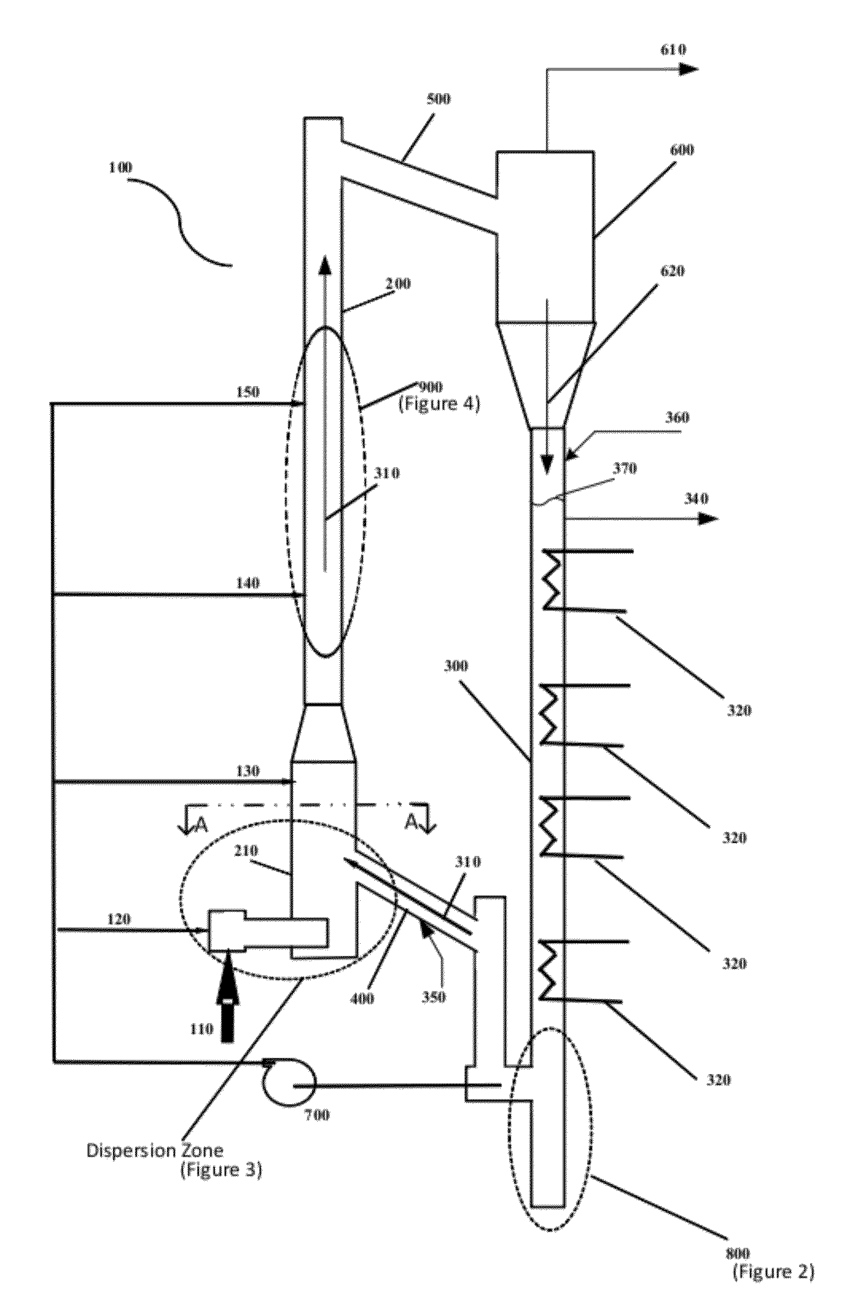
[0102]Described below is one non-limiting example of an exemplary embodiment of the disclosure. None of the descriptions, ranges, or other information in this example limit the scope and operation of the present invention. The hydrodynamics of the DBR riser in FIG. 1 was tested up to 480 pounds per square inch gauge (psig) and by varying the riser superficial gas velocities from 3 to 35 ft / s. The DBR operation was characterized using pressure drop, gas hold-up, liquid circulation rates, and flow regimes. The tests showed that using the static head in the standpipe as the driving force, the circulating liquid and the gas stream entering the riser could produce a stable dispersed bubble flow regime in the riser with the creation of a large interfacial area for gas-liquid contact.

[0103]For a particular pilot test apparatus, the liquid circulation rate varied with the gas flow rate in the riser and reached a maximum at 10 ft / s, as predicted. The bulk density in the riser was in the rang...


PUM

PropertyMeasurementUnit
velocityaaaaaaaaaa
velocityaaaaaaaaaa
sizeaaaaaaaaaa

Abstract

An apparatus to promote gas-liquid contact and facilitate enhanced mass transfer. The dispersed bubble reactor (DBR) operates in the dispersed bubble flow regime to selectively absorb gas phase constituents into the liquid phase. The dispersion is achieved by shearing the large inlet gas bubbles into fine bubbles with circulating liquid and additional pumped liquid solvent when necessary. The DBR is capable of handling precipitates that may form during absorption or fine catalysts that may be necessary to promote liquid phase reactions. The DBR can be configured with multistage counter current flow sections by inserting concentric cylindrical sections into the riser to facilitate annular flow. While the DBR can absorb CO2 in liquid solvents that may lead to precipitates at high loadings, it is equally capable of handling many different types of chemical processes involving solids (precipitates/catalysts) along with gas and liquid phases.

Description

CROSS-REFERENCE TO RELATED APPLICATIONS[0001]This application claims the benefit of U.S. Provisional Application No. 61 / 446,870 filed 25 Feb. 2011, the entire contents and substance of which are hereby incorporated by reference.STATEMENT REGARDING FEDERALLY SPONSORED RESEARCH OR DEVELOPMENT[0002]This invention was made with Government support under Cooperative Agreement Number DE-NT0000749 awarded by the United States Department of Energy. The United States government has certain rights in the invention.BACKGROUND OF THE INVENTION[0003]1. Field of the Invention[0004]The present invention relates generally to reactors involving gas-liquid-solid phases, and more particularly to a dispersed bubble reactor (DBR) that removes CO2 from gas streams through enhanced gas-liquid contact and mass transfer, which DBR is capable of handling relatively fine solid particles with relatively high throughputs.[0005]2. Description of Related Art[0006]Conventional gas-liquid contacting equipment in pra...

Claims


Application Information

Patent Timeline
Patent Type & Authority Applications(United States)
IPC IPC(8): B01D53/14B01F3/04
CPCB01D53/1475Y02C10/06B01D53/62B01D2251/206B01J8/1827B01J8/1836B01J8/1872B01J8/228B01J19/1881B01J2208/00141B01J2208/00548B01J2219/00083B01J2219/00164B01J2219/00182B01J2219/00247Y02C10/04B01D53/18Y02P20/151Y02A50/20Y02C20/40
Inventor VIMALCHAND, PANNALALLIU, GUOHAIPENG, WANWANGBONSU, ALEXANDER
Owner THE SOUTHERN CO
Why Eureka
Try Eureka