Brazing process

a brazing process and process technology, applied in the field of joining, can solve the problems of limited use of ceramic components, weak joints at the joins of smaller parts, and large or complex ceramic components, and achieve the effect of reducing the porosity of the preform

Inactive Publication Date: 2012-09-06
CERAMIC FUEL CELL LTD
View PDF6 Cites 2 Cited by
  • Summary
  • Abstract
  • Description
  • Claims
  • Application Information

AI Technical Summary

Benefits of technology

[0049]The consolidation and heating processes used to produce such a high density ribbon, strip or gasket means that use of the filler at a later time is more convenient. During the

Problems solved by technology

However, their use is limited by the current inability to economically manufacture large or complex ceramic components comprising a number of smaller parts.
The smaller ceramic parts can be easily formed, but weaknesses often exist at the joins between the smaller parts.
Ceramic oxide surfaces are inherently difficult to wet with molten brazing fillers comprising a noble metal.
One of the most widely used methods of metallisation involves applying a powder mixture of glass, molybdenum and manganese to the ceramic surface and heating it in a damp hyd

Method used


Image

  • Brazing process
  • Brazing process
  • Brazing process

Examples


example 1

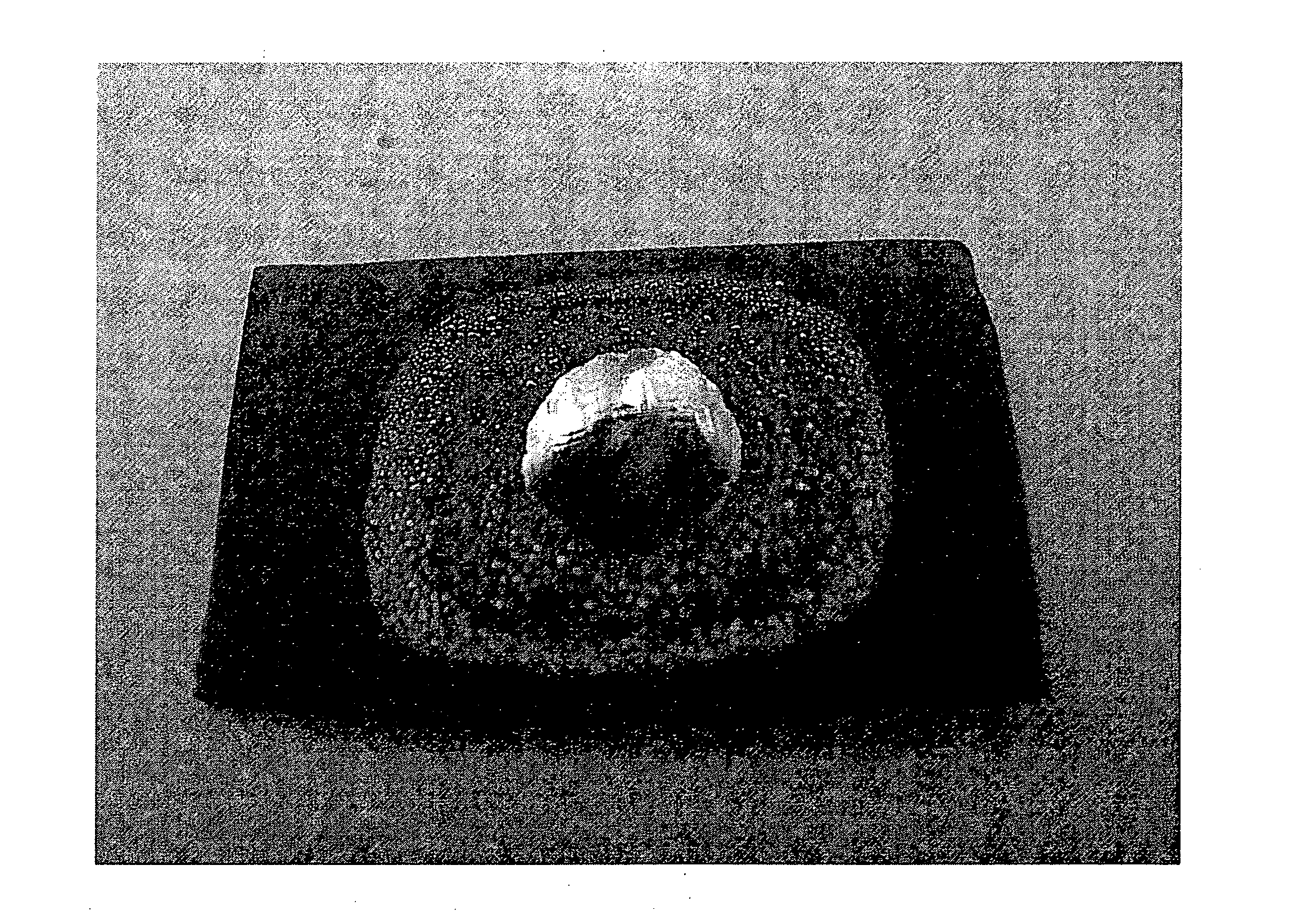
[0066]A powder of silver metal was mixed with Cerdec™80683 binder to form a slurry (in the absence of second metal). The silver particles were sized less than 44 μm. Small droplets of the slurry (about 0.1 ml) were placed on a ceramic oxide surface comprising yttria stabilised zirconia (YSZ).

[0067]The surface having the filler thereon was heated in air to about 970° C. until molten for a period of about 30 minutes. The surface was then cooled to room temperature. FIG. 1 shows the small beads of silver that result on the ceramic oxide surface. The beading of the silver indicates that the silver did not spread over or wet the ceramic surface under the heating conditions. Visual inspection shows that the silver was poorly bonded to the ceramic oxide surface.

[0068]Another YSZ surface having droplets of a filler comprising only silver thereon was heated in air to about 975° C. for a period of about 30 minutes (in the absence of a second metal). The surface was then cooled to room tempera...

example 2

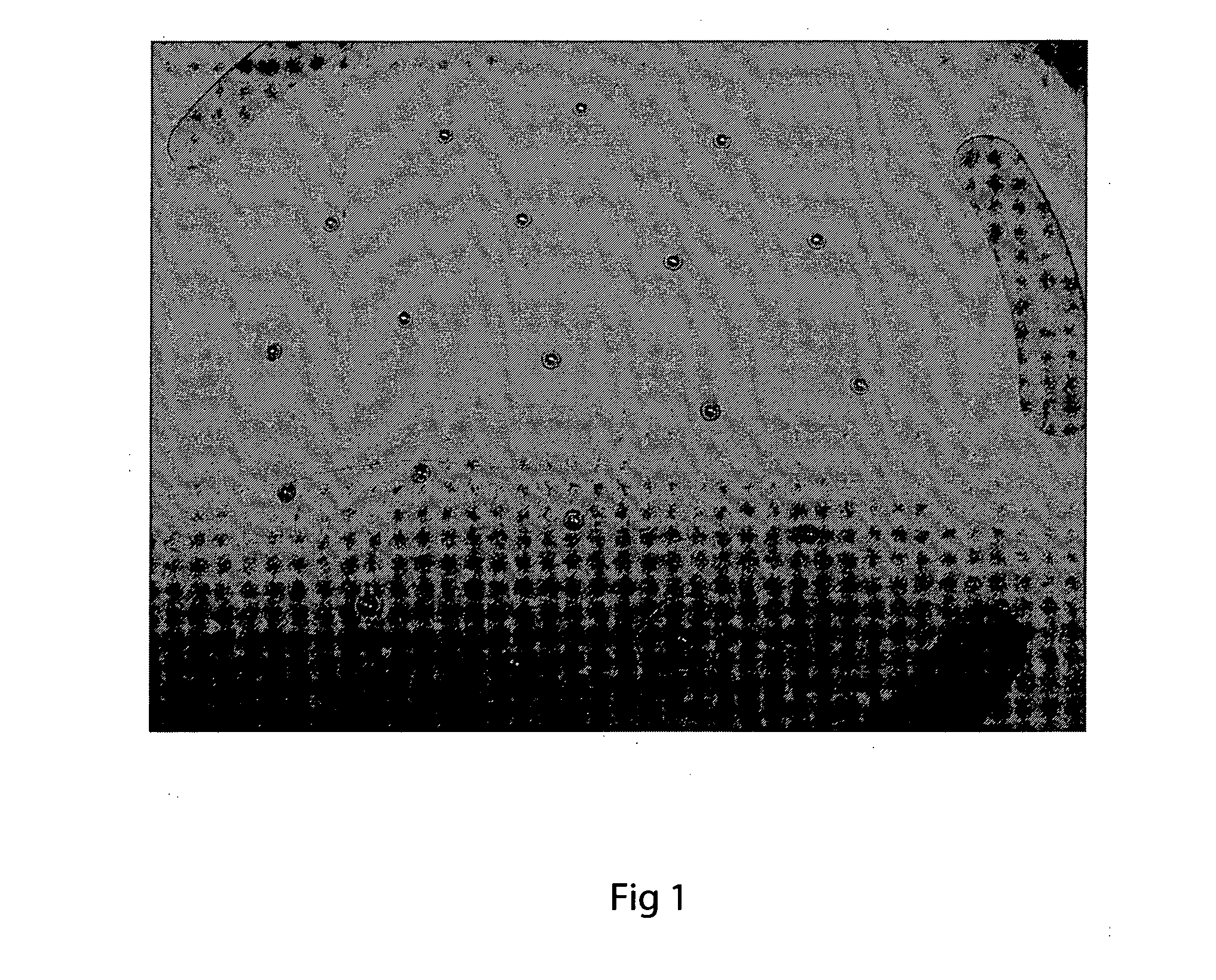
[0069]In order to demonstrate that a second metal added to the filler can improve its ability to wet a ceramic oxide surface, a further powder comprising aluminium was added to the silver powder during preparation of the filler. The powder mixture comprised about 0.2 wt % of aluminium (not including the weight of the binder). The aluminium had an average particle size of 5 μm. The two powders (silver and aluminium) were mixed by stirring together with the binder to form a slurry. Stirring can be done by hand or by means of a mechanical stirrer.

[0070]Small droplets of about the same size as those of Example 1 were placed on the same type of ceramic oxide surface used in Example 1. The surface was heated in air to above the melting point of the silver (i.e. to 975° C.) for about 30 minutes and then cooled.

[0071]FIG. 3 shows that a filler comprising about 0.2 wt % aluminium has a decreased contact angle with the ceramic oxide surface (compared to the same filler in the absence of the a...

example 3

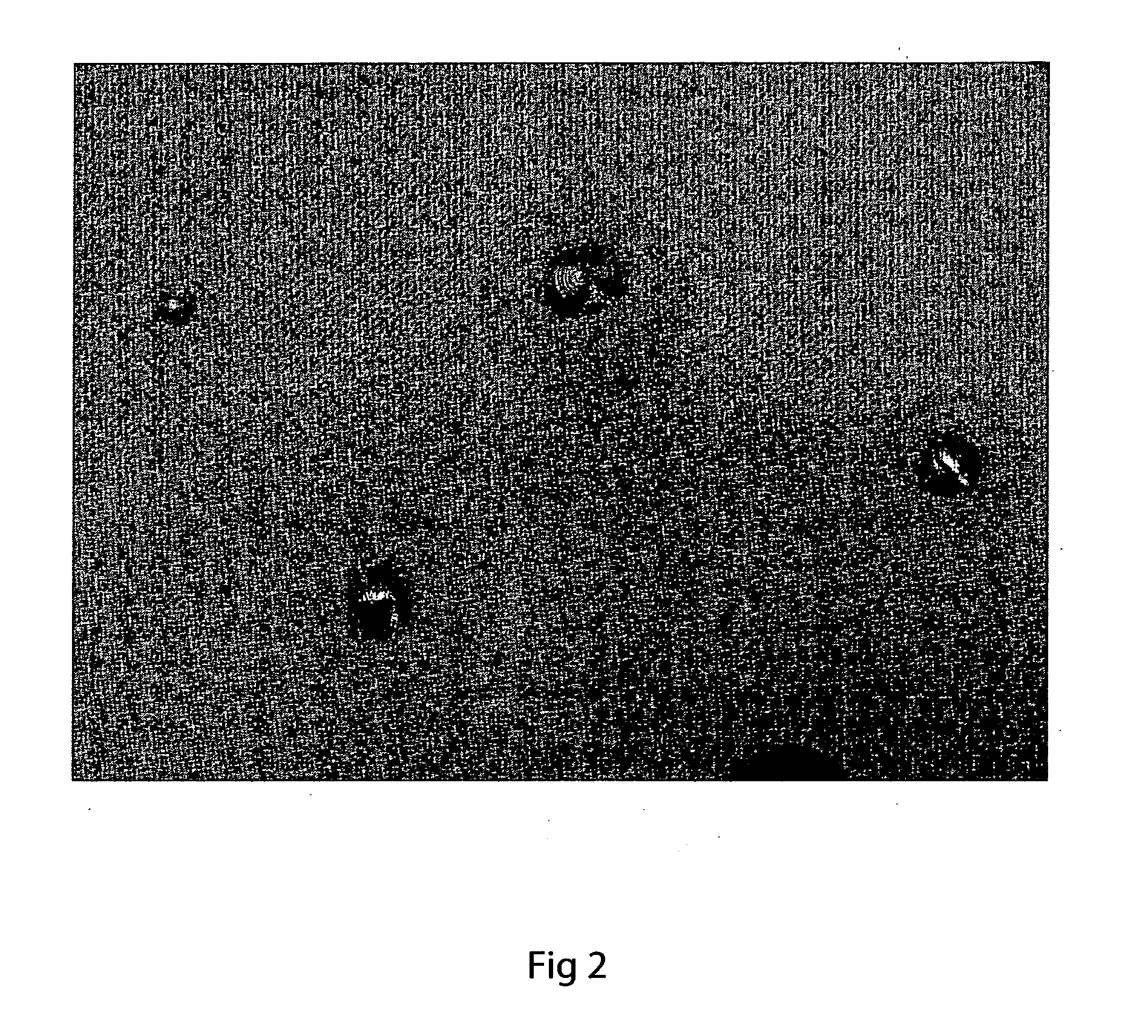
[0072]In order to demonstrate that another amount of a second metal added to the filler can improve the wettability of a ceramic oxide surface, 0.4 wt % of the aluminium powder was added to the silver powder during preparation of the filler. Using the same conditions as described in Example 2, except that the heating temperature was 970° C. (which difference is believed to be relatively inconsequential), the filler was melted on the YSZ ceramic surface and then cooled. The increased wettability of the filler on the ceramic oxide, due to the formation of aluminium oxide at the molten filler / vapour interface, is shown in FIG. 4. The cooled filler was well bonded to the ceramic oxide surface.


PUM

PropertyMeasurementUnit
Melting pointaaaaaaaaaa
Particle diameteraaaaaaaaaa

Abstract

A brazing process for joining at least two components having ceramic oxide surfaces is described. The brazing filler used in the process comprises a noble metal and a second metal. During the brazing process, the filler is heated in an oxidising atmosphere such as air. The heating is undertaken until at least the noble metal is molten. The molten filler comprises a surface oxide formed from a stable, non-volatile oxide of the second metal that does not significantly alloy with the molten noble metal. The molten filler is able to wet the ceramic oxide surfaces and is subsequently cooled between them to thereby join them together.

Description

PRIORITY[0001]This application claims priority from AU 2009903255, which is hereby incorporated herein in its entirety.FIELD OF THE INVENTION[0002]The present invention relates to the joining of components comprising ceramic oxide surfaces.BACKGROUND[0003]Ceramics have excellent mechanical properties such as robustness and corrosion resistance. However, their use is limited by the current inability to economically manufacture large or complex ceramic components comprising a number of smaller parts. The smaller ceramic parts can be easily formed, but weaknesses often exist at the joins between the smaller parts.[0004]Ceramic-based solid oxide fuel cell stacks comprise ceramic components or metal components having ceramic oxide surfaces that require joins which hermetically seal with other components in the stack including those having metal and other ceramic surfaces. Since the fuel cell functions due to the oxygen ion gradient that develops across the electrolyte membrane, for the f...

Claims


Application Information

Patent Timeline
IPC IPC(8): B32B18/00B23K1/00
CPCB23K35/025B23K35/3006B23K35/3013Y02E60/525H01M8/0286H01M2008/1293Y02E60/50B23K35/322
Inventor ZHENG, PAUL
Owner CERAMIC FUEL CELL LTD
Why Eureka
Try Eureka