
Liquid crystal optical device and its production process

a technology of optical devices and liquid crystals, applied in the manufacture of electrode systems, electric discharge tubes/lamps, instruments, etc., can solve the problems of unstable holding of liquid crystal alignment, greatly affecting the optical properties of liquid crystal optical devices, and affecting the reliability and production process. , to achieve the effect of excellent reliability and production process

Inactive Publication Date: 2012-10-25
OPTREX CORP +1
View PDF4 Cites 10 Cited by
  • Summary
  • Abstract
  • Description
  • Claims
  • Application Information

AI Technical Summary

Benefits of technology

[0032]According to the liquid crystal optical device of the present invention, a molecular motion (such as rotational, translational and vibrational motion) of a curable moiety can be improved by introducing favorable length alkylene group (R1 and R2) between the mesogen structure and each of the curable functional group (A1 and A2) by means of an O atom in the curable compound. As a result, the curable compound can be cured by a low irradiation energy for adequate curing. Further, since the molecular motion of the curable moiety during the curing is improved to increase the curing reactivity of the curable compound, the amount of the residual uncured curable compound in the liquid crystal layer can be reduced. Further, by using the curable compound of the above formula (1), after curing, the thermoplastic property of a cured material can be suppressed. As a result, a polymer structure showing elastic deformation can be obtained. Accordingly, the liquid crystal optical device excellent in the reliability can be provided.
[0034]According to the present invention, a liquid crystal optical device excellent in the reliability and its production process can be provided.

Problems solved by technology

After curing of the curable compound, in case that the amount of the unreacted curable compound remaining in a liquid crystal layer is large, a optical properties of the liquid crystal optical device are greatly affected, such that holding of the liquid crystal alignment might become unstable over time.
Further, in a case a shape stability of the polymer structure is poor, the optical properties of the liquid crystal optical device are greatly affected in the same manner.
In the above Patent Document 5 also, there is a problem in view of a reliability.
That is, by an increase in the absorption coefficient in the ultraviolet region and in the short wavelength visible region, deterioration or decomposition of the liquid crystal may occur by the incident light, thus leading to a decrease of a resistivity and a decrease of a voltage holding ratio, and thus the reliability of the liquid crystal optical device may be decreased.
However, since the liquid crystalline monomer is mono-functional and the counter end of molecule is a long alkyl chain, a polymer of the liquid crystalline monomer shows a thermoplastic property, or it is difficult to sufficiently increase a elastic modulus of the polymer in some cases.
Accordingly, the alignment direction of liquid crystal molecules might not be stabilized in a wide temperature range, or a stability of the regulation of liquid crystal alignment might be impaired over time.

Method used


Image

  • Liquid crystal optical device and its production process
  • Liquid crystal optical device and its production process
  • Liquid crystal optical device and its production process

Examples


first embodiment

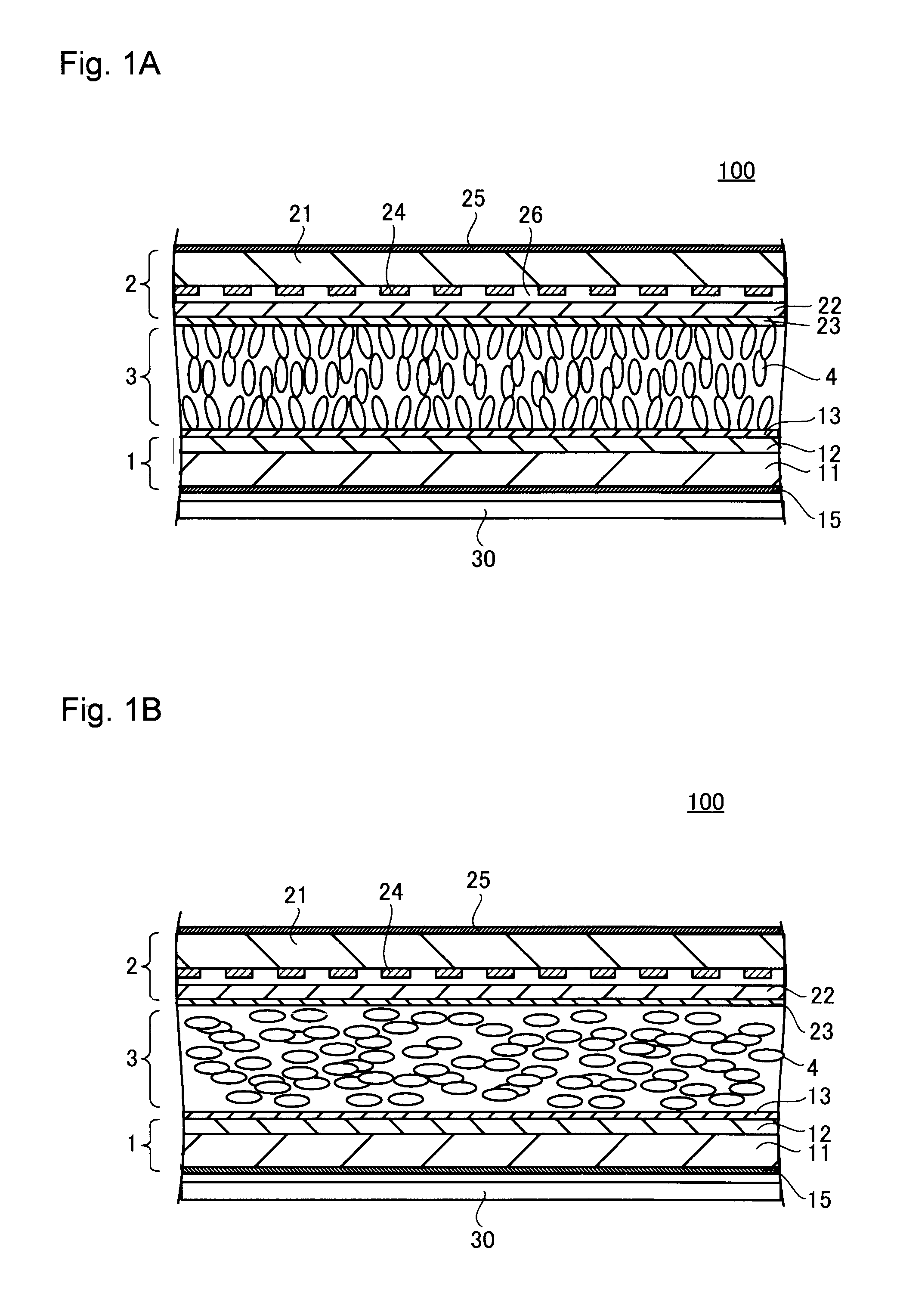
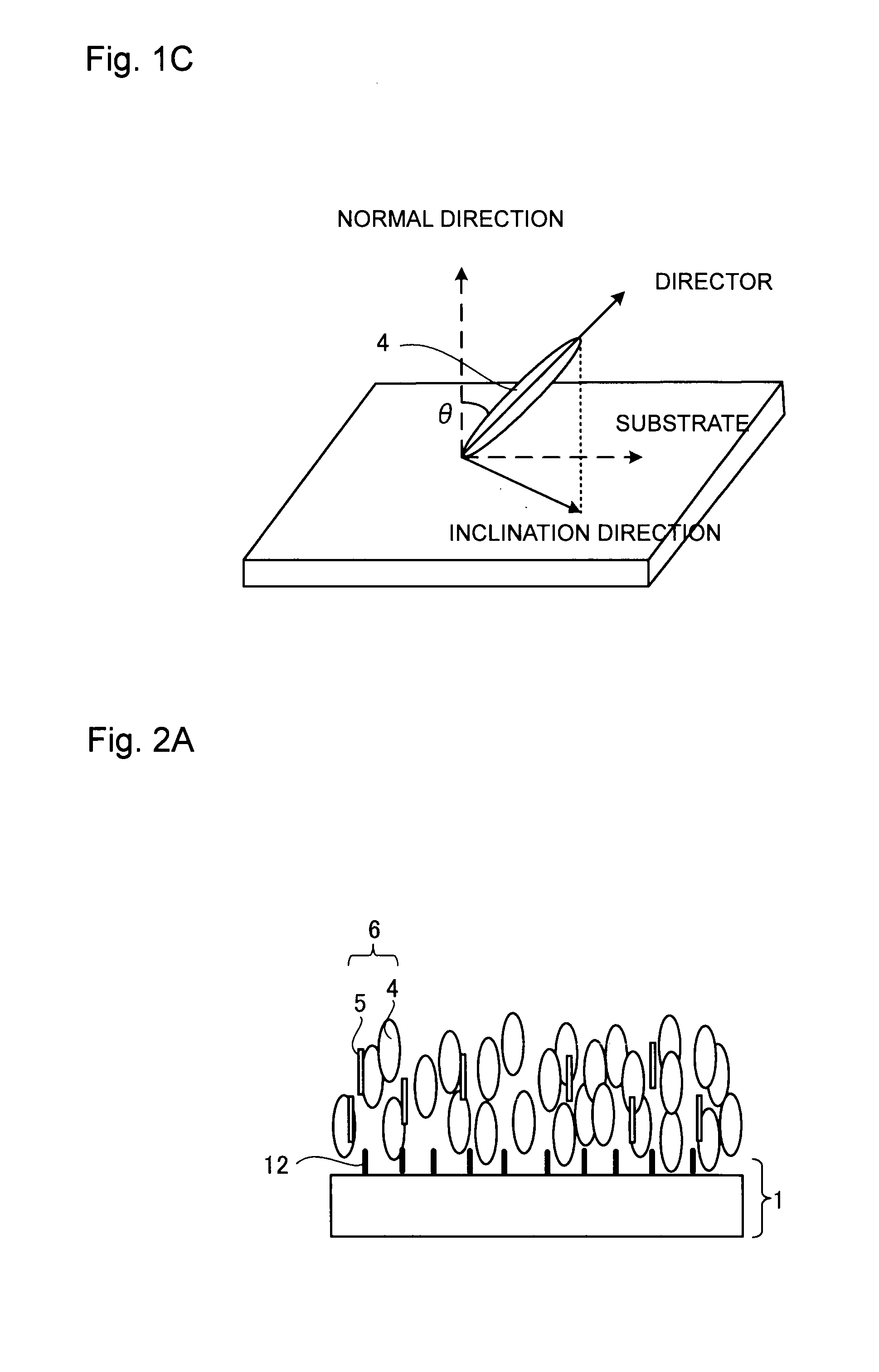
[0045]As a liquid crystal optical device according to a first embodiment, one example of a VA (Vertical Alignment) mode active matrix type liquid crystal display device will be described. FIG. 1A is a cross-sectional view schematically illustrating a substantial part of a liquid crystal display device according to the first embodiment when a voltage is not applied, and FIG. 1B is a cross-sectional view schematically illustrating a substantial part when a voltage is applied. Further, FIG. 1C is a view schematically illustrating the alignment of liquid crystal. Here, a transmission type liquid crystal display device will be described. Instead of the transmission type, a reflection type or semi-transmission type liquid crystal display device may also be used. Further, the device is also applicable to a passive type instead of an active matrix type.

[0046]A liquid crystal display device 100 has a pair of a first substrate 1 (e.g. a TFT substrate) and a second substrate 2 (e.g. a color fi...

second embodiment

[0090]As a liquid crystal optical device according to a second embodiment, one example of a liquid crystal light control device will be described. In the following drawings, to the same components as in the above first embodiment, the same symbols are attached and their description is omitted.

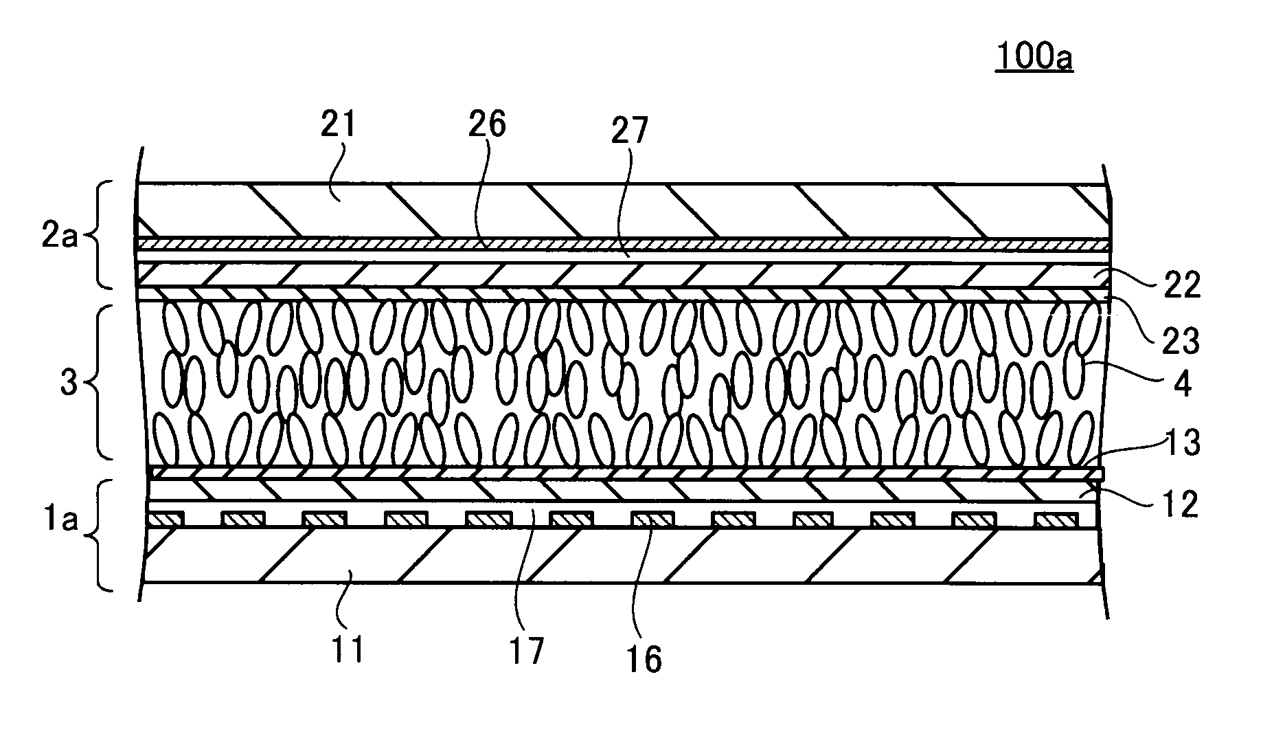
[0091]FIG. 3 is a cross-sectional view schematically illustrating a substantial part of a liquid crystal light control device according to a second embodiment when a voltage is not applied. A liquid crystal light control device 100a according to the second embodiment is in a transparent state when a voltage is not applied and is in a uniformly light scattering state when a voltage is applied.

[0092]The liquid crystal light control device 100a comprises, as shown in FIG. 3, a transparent first substrate 1a and a transparent second substrate 2a disposed to face each other. Both the substrates are bonded by means of a sealing material (not shown) provided on the periphery of the pair of substrates,...

example 1

[0100]An evaluation cell was prepared by the following method. Specifically, a polyimide thin layer for vertical alignment was formed on a clean ITO transparent electrode, and rubbing treatment was applied to the surface of substrate so as to impart a very fine pretilt angle, thereby to prepare a pair of substrates. Then, the substrates were bonded so that the polyimide thin layer formed on the surface of substrate faced each other to prepare the evaluation cell. The pretilt angle of the alignment layer of the liquid crystal cell was at most 0.5° when the pretilt angle in the direction vertical to the surface of substrate is 0°, and the cell gap was 2.7 μm.

[0101]Then, a nematic liquid crystal (Δε=−2.1, Δn=0.116, nematic-isotropic phase transition temperature=103.4° C., viscosity=18.8 mPa·s) having a negative dielectric constant anisotropy for VA-liquid crystal display, a curable compound represented by the formula (4) and benzoin isopropyl ether (BiPE, manufactured by TOKYO CHEMICAL...


PUM

PropertyMeasurementUnit
distanceaaaaaaaaaa
pretilt angleaaaaaaaaaa

Abstract

A liquid crystal optical device comprising a pair of substrates having an electrode pair formed; a liquid crystal layer sandwiched between the substrates; an alignment layer to align the liquid crystal, provided on each of the facing surfaces of the substrates; and a polymer structure provided on the alignment layer; wherein the polymer structure is formed by curing a curable compound represented by the following formula (1), and when a voltage is not applied, liquid crystal molecules in the vicinity of an interface between the liquid crystal layer and the polymer structure have at least one direction of director different from the alignment direction by the alignment layer:A1-O—R1—O—Z—O—R2—O-A2   Formula (1)wherein each of A1 and A2 is independently a curable functional group to be polymerized by an external energy, each of R1 and R2 is independently selected from a linear alkylene group with carbon number of 2 to 5 which may have a methyl group or an ethyl group as a branched chain, and Z is a bivalent mesogen structure.

Description

BACKGROUND OF INVENTION[0001]1. Field of Invention[0002]The present invention relates to a liquid crystal optical device of which the transmission state is controlled depending on the application of a voltage, such as a liquid crystal optical shutter, a liquid crystal light control device or a liquid crystal display device, and its production process.[0003]2. Discussion of Background[0004]A liquid crystal optical device has established a firm position as a display device for a display of e.g. a TV, a personal computer and a car navigation system. Further, its application to a light control device has also been attempted. A liquid crystal optical device usually has a structure in which a liquid crystal layer is sandwiched between a pair of substrates. As one method of forming a liquid crystal layer, attention has been paid to a method of injecting a liquid crystal composition containing liquid crystal and a curable compound to between a pair of substrates, and subjecting the curable ...

Claims


Application Information

Patent Timeline
Patent Type & Authority Applications(United States)
IPC IPC(8): G02F1/1337H01J9/24G02F1/1335
CPCG02F1/133711G02F1/133753G02F2202/023G02F1/133742
Inventor KAWAKAMI, REMINIIYAMA, SATOSHINAKAGAWA, YUTAKASODA, YUJI
Owner OPTREX CORP
Learn More