Diffusion Furnaces Employing Ultra Low Mass Transport Systems and Methods of Wafer Rapid Diffusion Processing

a diffusion furnace and ultra-low mass transport technology, applied in the direction of furnaces, lighting and heating apparatus, charge supports, etc., can solve the problems of reducing cell efficiency or power output, cell efficiency loss, cell efficiency loss, etc., to achieve the effect of exceeding the safe operation value and improving lateral heating uniformity across the width of the furna

Inactive Publication Date: 2012-10-25
TP SOLAR OF USA
View PDF3 Cites 23 Cited by
  • Summary
  • Abstract
  • Description
  • Claims
  • Application Information

AI Technical Summary

Benefits of technology

[0061]In the presently-preferred heating system, transversely oriented IR lamps are used in the upper heating zone(s), and a combination of IR lamps and resistance heating is used in the lower heating zone. To improve lateral heating uniformity across the width of the furnace, resistance heaters are placed adjacent the two longitudinal side walls oriented parallel to and spaced apart from the centerline of the furnace, while the IR lamps are placed transversely above or below the longitudinal side wall resistance heating elements, preferably below. The longitudinal side wall resistance heaters are disposed in, and supported by, quartz, ceramic or stabilized SiC tubes disposed just below the conveyor. In a 5-Lane or wider furnace they serve to keep the wafers in Lanes 1 and 5, the outer lanes adjacent the respective side

Problems solved by technology

However, the formation of such contacts is at the expense of a loss in cell efficiency.
The cell efficiency loss arises as a result of electron-hole pairs generated at or near the surface through the absorption of higher energy but short wave length photons.
The defects are traps where electron-hole pairs can recombine thereby reducing cell efficiency or power output.
However, the tubes are expensive, add mass to the conveyor system and block access to the lower heating zone of the furnace.
However, in a Bottom Drop furnace, the tube supports move down with the lower half of the furnace while the conveyor belt remains suspended, so the conveyor cannot be operated when open.
With respect to adding furnaces, conventional furnaces have a large footprint and the diffusion process is very slow.
Running them at greater power levels would easily raise the temperature higher than needed for diffusion, and approach failure of metallic components (e.g., in the roller drive elements secured to the ends of the rollers).
Thus, since the furnaces are large, adding furnaces requires increased capital outlay, for buildings, the furnaces themselves, and related servic

Method used


Image

  • Diffusion Furnaces Employing Ultra Low Mass Transport Systems and Methods of Wafer Rapid Diffusion Processing
  • Diffusion Furnaces Employing Ultra Low Mass Transport Systems and Methods of Wafer Rapid Diffusion Processing
  • Diffusion Furnaces Employing Ultra Low Mass Transport Systems and Methods of Wafer Rapid Diffusion Processing

Examples


first embodiment

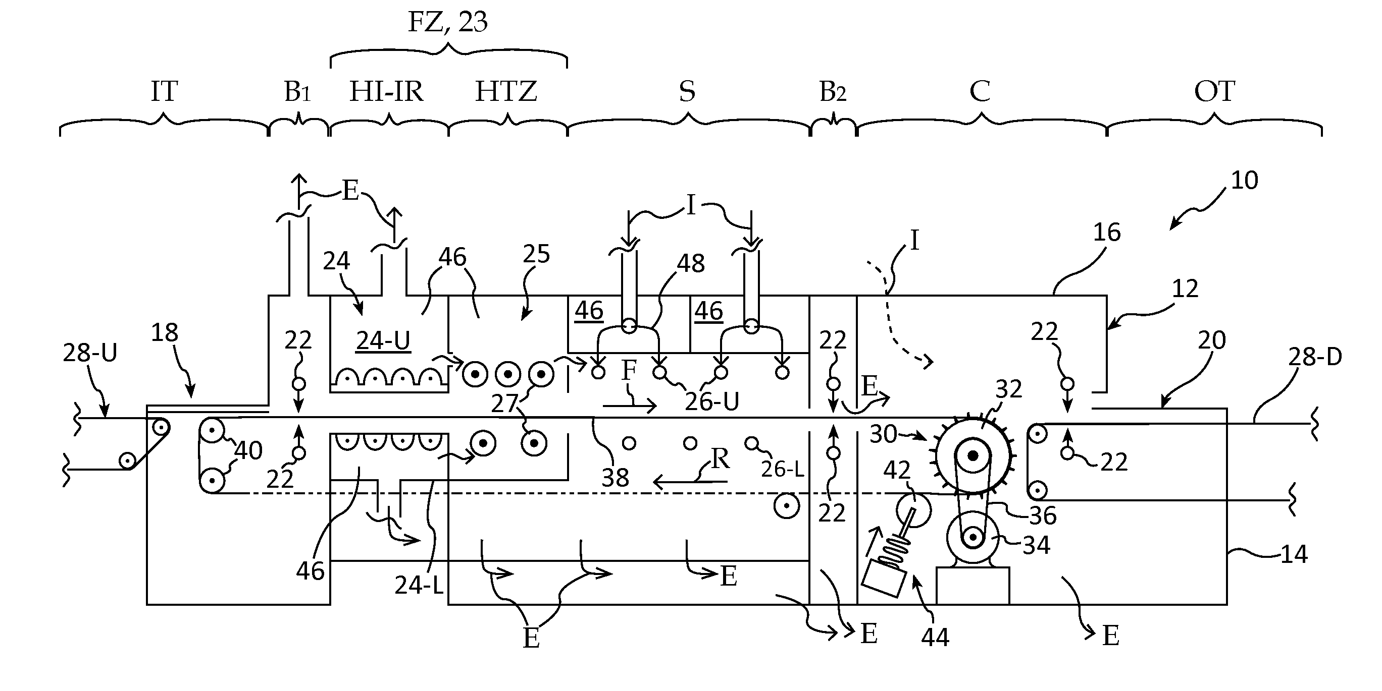
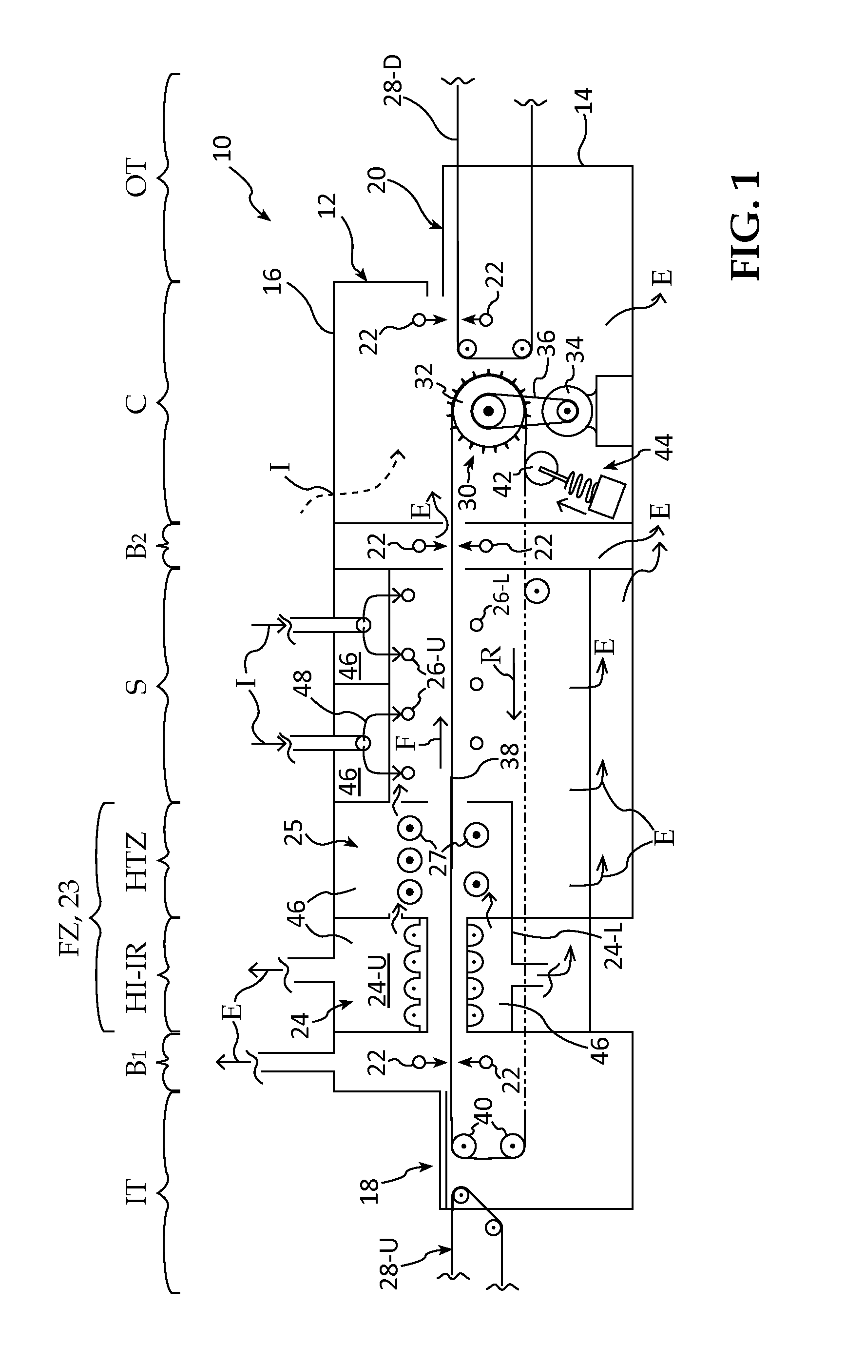
[0101]The inventive furnace low-mass drive system 30, in a first embodiment, comprises a pin drive roller 32, driven by a motor 34 and chain or belt 36 disposed at the outlet (right) end of the furnace, wafer transport band assemblies 38, idler rollers 40 and a tension system 44 which includes a tension roller 42. The tension system 44 includes an automatic tension compensator spring acting as a dashpot to assist in preventing surges. Note that by this drive geometry, the bands 38 are pulled along the feed path, F, through the zones from left to right. This is implemented by the drive assembly 30 pulling the upper level bands from left to right (as indicated by Arrow F—forward).

[0102]The inventive furnace includes a plurality of plenums defining the Zones interior of the housing 12, and a plurality of air manifolds, including inlets and exhausts for ambient or pressurized air flow into the various Zones as shown by the arrows I (for Inlet), and E (for Exhaust), in order to maintain ...

second embodiment

[0126]FIGS. 7-10B are directed to the inventive ultra low mass transport system as employing a pair of spaced chains from which the wafer support wires and ceramic tubes are suspended. In FIG. 7, the description above for FIG. 1 applies for the parts numbered the same. Note that the IT and B1 zones are combined in this embodiment into a Ramp-Up Zone wherein the wafer temperature is raised from Room Temperature to about 500° C. to 900° C., the latter where the Ramp-Up Zone includes a HI-IR isolation lamp module. This is followed by the Firing Zone which raises the temperature to the diffusion processing temperature of about 950-1100° C., dependent on if P, or B, or both, are being diffused. As shown, the Firing Zone employs the disclosed exemplary resistive SiC elements. Firing set point temperature is retained in the Soaking Zone, the heating elements not being shown to prevent cluttering the drawing, but see FIGS. 1 and 5. As shown, the Cooling Zone is divided into two sub-zones, C...


PUM


Abstract

Multi-zone, solar cell diffusion furnaces having a plurality of radiant element (SiC) or/and high intensity IR lamp heated process zones, including baffle, ramp-up, firing, soaking and cooling zone(s). The transport of solar cell wafers, e.g., silicon, selenium, germanium or gallium-based solar cell wafers, through the furnace is implemented by use of an ultra low-mass, wafer transport system comprising laterally spaced shielded, synchronously driven, metal bands or chains carrying non-rotating alumina tubes suspended on wires between them. The wafers rest on raised circumferential standoffs spaced laterally along the alumina tubes, which reduces contamination. The high intensity IR flux rapidly photo-radiation conditions the wafers so that diffusion occurs>3× faster than conventional high-mass thermal furnaces. Longitudinal side wall heaters comprising coil heaters in Inconel sheaths inserted in carrier tubes are employed to insure even heating of wafer edges adjacent the side walls.

Description

CROSS-REFERENCE TO RELATED CASES[0001]This application is a Divisional and a CIP of Regular U.S. patent application Ser. No. 13 / 213,503 filed Aug. 19, 2011 by the same inventors under the same title, now U.S. Pat. No. 8,______ issued on ______, 2012, which in turn is a Divisional and CIP of Regular U.S. patent application Ser. No. 12 / 761,632, filed Apr. 16, 2010, by the same inventors under the same title, now U.S. Pat. No. 8,039,289 issued on Oct. 18, 2011, which in turn claims the benefit of U.S. Provisional Application Ser. No. 61 / 170,051 filed by the same inventors on Apr. 16, 2009, entitled Diffusion Furnace Having Low Mass Band Transport System and Rapid Diffusion Process Using High Intensity IR Flux, the benefit of the filing dates of these applications is hereby claimed under 35 US Code, Sections119 ff.FIELD[0002]The invention relates to continuous conveyor, multi-lane diffusion furnaces for processing solar cell wafers by use of radiant resistance or / and IR lamp heating in ...

Claims


Application Information

Patent Timeline
IPC IPC(8): F27D9/00
CPCF27B9/20F27B9/243F27B17/0025F27D5/0037H01L21/2254H01L31/18H01L21/67109H01L21/67115H01L21/67173H01L21/67706H01L21/6776H01L21/324
Inventor PARKS, RICHARD W.REY GARCIA, LUIS ALEJANDRORAGAY, PETER G.
Owner TP SOLAR OF USA
Why Eureka
Try Eureka