Charged particle system comprising a manipulator device for manipulation of one or more charged particle beams

a charge particle and beam technology, applied in the field of charge particle systems, can solve the problems of difficult arrangement of electrical circuits for controlling many manipulators in the lithography system, errors in the manipulation of beams, and difficult production of close-spaced arrays, etc., and achieve optimal balance and difficulty in production

Active Publication Date: 2012-11-01
ASML NETHERLANDS BV
View PDF32 Cites 55 Cited by
  • Summary
  • Abstract
  • Description
  • Claims
  • Application Information

AI Technical Summary

Benefits of technology

[0037]When adjacent electrodes are provided closer to each other, the generated electrical field could be more homogeneous. However, this is also more difficult to produce. It appears that with an electrode-to-gap ratio being in the range of 5-15, or preferably substantially 10, the two effects are optimally balanced.
[0038]In an embodiment of the charged particle system according to the invention, the manipulator comprises a cross-talk shield, the cross-talk shield comprising a planar shield substrate comprising at least one through opening in the plane of the planar shield substrate, wherein the at least one through opening of the planer shield substrate is arranged in alignment with the at least one through opening of the planar substrate. An advantage of a cross-talk shield is that it prevents to some extend cross-talk between electrodes of the same through opening, between electrodes of different through openings and / or between an electrode and other circuitry present in the vicinity of the electrode.

Problems solved by technology

However, any manipulator device for such closely spaced plurality of charged particle beamlets requires closely spaced arrays of manipulators.
Such closely spaced arrays are difficult to produce.
In particular electrical circuits for controlling many manipulators are difficult to arrange in the lithography system.
In addition, cross-talk between manipulators and other circuits in the vicinity of the manipulators can cause errors in the manipulation of the beams.
Furthermore, it can be difficult to produce a manipulator device that is able to manipulate the charged particle beam with sufficient accuracy.
Any misalignment of the charged particle beam will then result in large manipulation errors.

Method used


Image

  • Charged particle system comprising a manipulator device for manipulation of one or more charged particle beams
  • Charged particle system comprising a manipulator device for manipulation of one or more charged particle beams
  • Charged particle system comprising a manipulator device for manipulation of one or more charged particle beams

Examples


Embodiment Construction

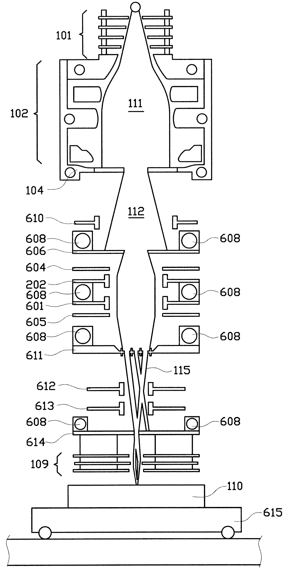
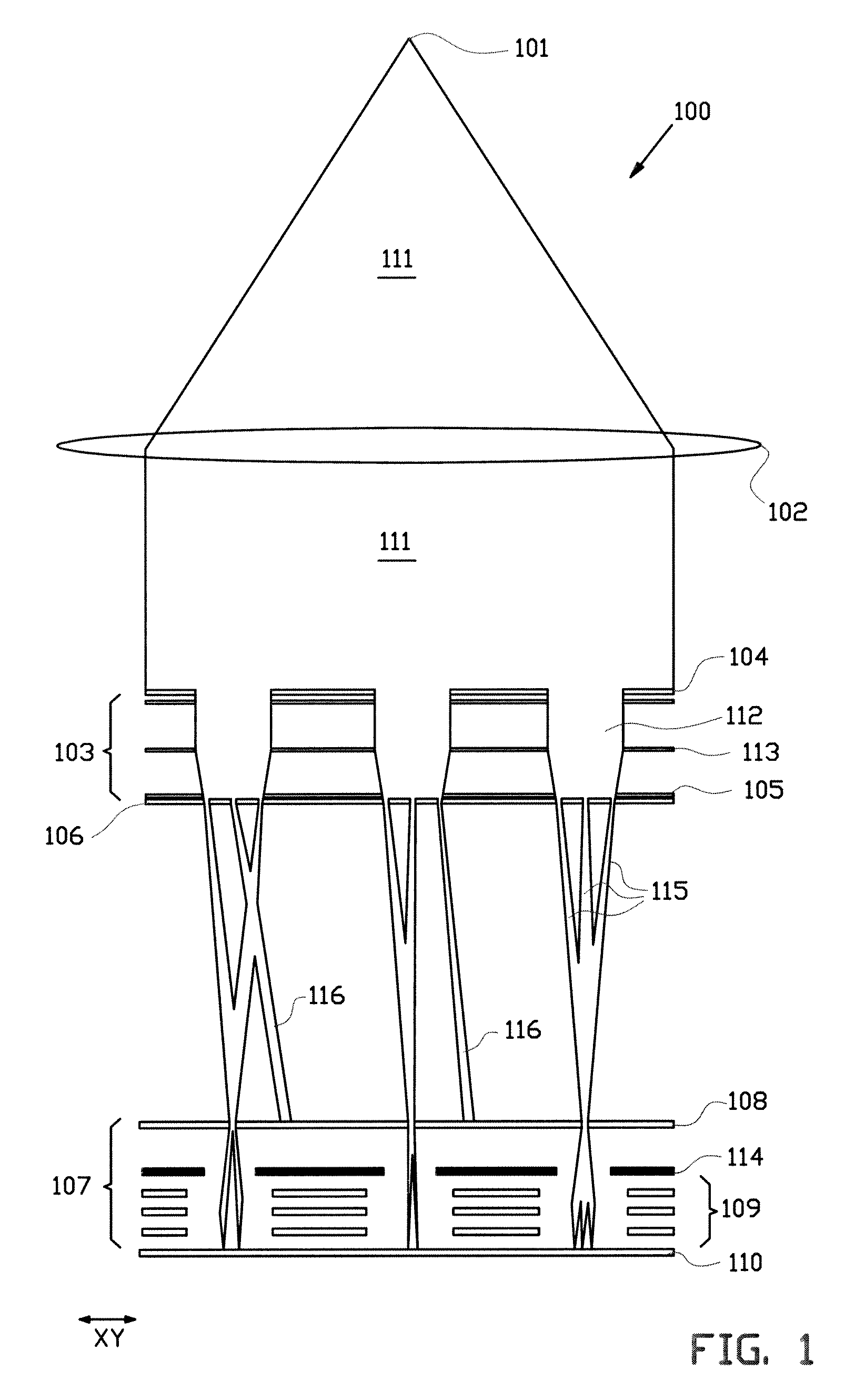
[0099]FIG. 1 shows a schematic overview of a part of a charged particle multi-beam or multi-beamlet lithography system 100 according to an embodiment of the invention for processing at least a part of a target 110, which may be a wafer. In an embodiment of the invention, the lithography system is without common cross-over of all the charged particle beams or beamlets and / or maskless.

[0100]The lithography system as shown in FIG. 1 comprises a charged particle source 101, for example an electron source, for producing an expanding charged particle beam 111. The expanding beam passes a collimator lens 102 for collimating the charged particle beam 111.

[0101]Subsequently the collimated beam 111 impinges on an aperture array 104, which blocks part of the collimated beam 111 for creating sub-beams 112. The sub-beams 112 impinge on a further aperture array 105 for creating beamlets 115. A condenser lens array 103 (or set of condenser lens arrays) is provided for focusing the sub-beams 112 to...


PUM


Abstract

The invention relates to a charged particle system such as a multi beam lithography system, comprising a manipulator device for manipulation of one or more charged particle beams, wherein the manipulator device comprises at least one through opening in the plane of the planar substrate for passing at least one charged particle beam there through. Each through opening is provided with electrodes arranged in a first set of multiple first electrodes along a first part of a perimeter of said through opening and in a second set of multiple second electrodes along a second part of said perimeter. An electronic control circuit is arranged for providing voltage differences the electrodes in dependence of a position of the first and second electrode along the perimeter of the through opening.

Description

BACKGROUND[0001]The invention relates to a charged particle system, such as a multi beam lithography system, comprising a manipulator device for manipulation of one or more charged particle beams.[0002]Charged particle systems, such as (multi) electron beam systems, are being developed for high throughput maskless lithography systems, (multi) electron beam microscopy and (multi) electron beam induced deposition devices. In particular for maskless lithography systems, individual beam modulation or manipulation is needed during the writing of a pattern on a substrate.[0003]Those lithography systems comprise either continuous sources or sources operating at constant frequency or at a varying frequency. Pattern data can be sent towards a manipulator device (or modulation means), which may be able to completely or partly stop the emitted beams from reaching the target exposure surface when necessary. The manipulator device (or modulation means) can also be provided for changing other cha...

Claims


Application Information

Patent Timeline
Patent Type & Authority Applications(United States)
IPC IPC(8): G21K5/04H01J3/26H01J3/14
CPCG03F7/2059H01J37/09H01J37/3177H01J2237/1205B82Y40/00H01J37/045H01J37/12B82Y10/00G03F7/70H01J37/317H01J37/22G03F7/20
Inventor WIELAND, MARCO JAN JACOKAREL STEENBRINK, STIJN WILLEM HERMANVINCENT VAN VEEN, ALEXANDER HENDRIKBROM, ALRIK VAN DEN
Owner ASML NETHERLANDS BV
Why Eureka
Try Eureka