Semiconductor device and fabrication method thereof

a semiconductor device and semiconductor technology, applied in the direction of semiconductor devices, basic electric elements, electrical equipment, etc., can solve the problems of strong electric field, and achieve the effect of reducing production costs and saving space on wafers

Active Publication Date: 2012-11-08
GPOWER SEMICON
View PDF5 Cites 32 Cited by
  • Summary
  • Abstract
  • Description
  • Claims
  • Application Information

AI Technical Summary

Benefits of technology

[0010]With such semiconductor device of the invention, since the source and drain comprise multiple fingers intersected with each other, which is to say, the source and the drain are embedded with each other, and the gate is located between the source and the drain and encircles the multiple fingers of the source and drain, the total gate width within unit area may be significantly increased. Because current density of the device is not affected by layout design, when the total gate width within unit area increases significantly, maximum saturation current within unit area will also increase significantly. Also, since the gate comprises a closed ring structure without beginning and ending, making the gate no starting point and ending point, the phenomenon of point discharge may be effectively avoided, which increases breakdown voltage of the device. In contrast, if the gate has an open ring structure, then at position of gate's starting point and ending point, due to point discharge effect, electric line of force will be too intensive at gate's starting point and ending point, resulting in very strong electric field. In addition, by forming the source and the drain into embedded structure intersected with each other, area on a wafer may be effectively utilized, thereby reducing production cost.
[0012]By employing an arc structure at respective corners of the gate and also employing an arc structure at source and drain at corresponding positions, variation of gate at corners are very gentle, and are not so abrupt as shape variation of tips at terminals 13A of the above linear-type gate 13. Since shape variation of gate in an arc structure is very gentle without sharp shape variation, the condition of very intensive electric line of force at certain tips will not occur, and thus point discharge due to sharp edge will not occur. Since the distribution of electric field is relatively uniform at these arc corners, and tips at terminal point of linear-type gate do not exist, it also avoids point discharge, effectively reduces electric field at corners of the gate and increases breakdown voltage of the device.
[0014]By making lead pad of the gate and that of the source to be at same side and lead pad of the drain to be at the other side, device damage due to the high voltage between gate and drain may be avoided. This is because there is a very high voltage difference (may be over one thousand volts) between gate and drain, and between source and drain, while the voltage difference between source and gate is relative small. If gate and drain are located at same side, the high voltage between gate and drain may cause device degradation or device breakdown.
[0016]The invention has no limitation on the number and width of fingers of the source and the drain. By making the width of the fingers of the source and the drain to be different, enough space will be left in certain regions within the source and drain to place lead pad of the source and that of the drain, so that there is no need to place lead pad at regions outside of the source and drain, and to lead an interconnection line or an air bridge is from the source and drain connecting the lead pads. Therefore, space on a wafer may be saved and production cost may be reduced.

Problems solved by technology

In contrast, if the gate has an open ring structure, then at position of gate's starting point and ending point, due to point discharge effect, electric line of force will be too intensive at gate's starting point and ending point, resulting in very strong electric field.

Method used


Image

  • Semiconductor device and fabrication method thereof
  • Semiconductor device and fabrication method thereof
  • Semiconductor device and fabrication method thereof

Examples


embodiment 1

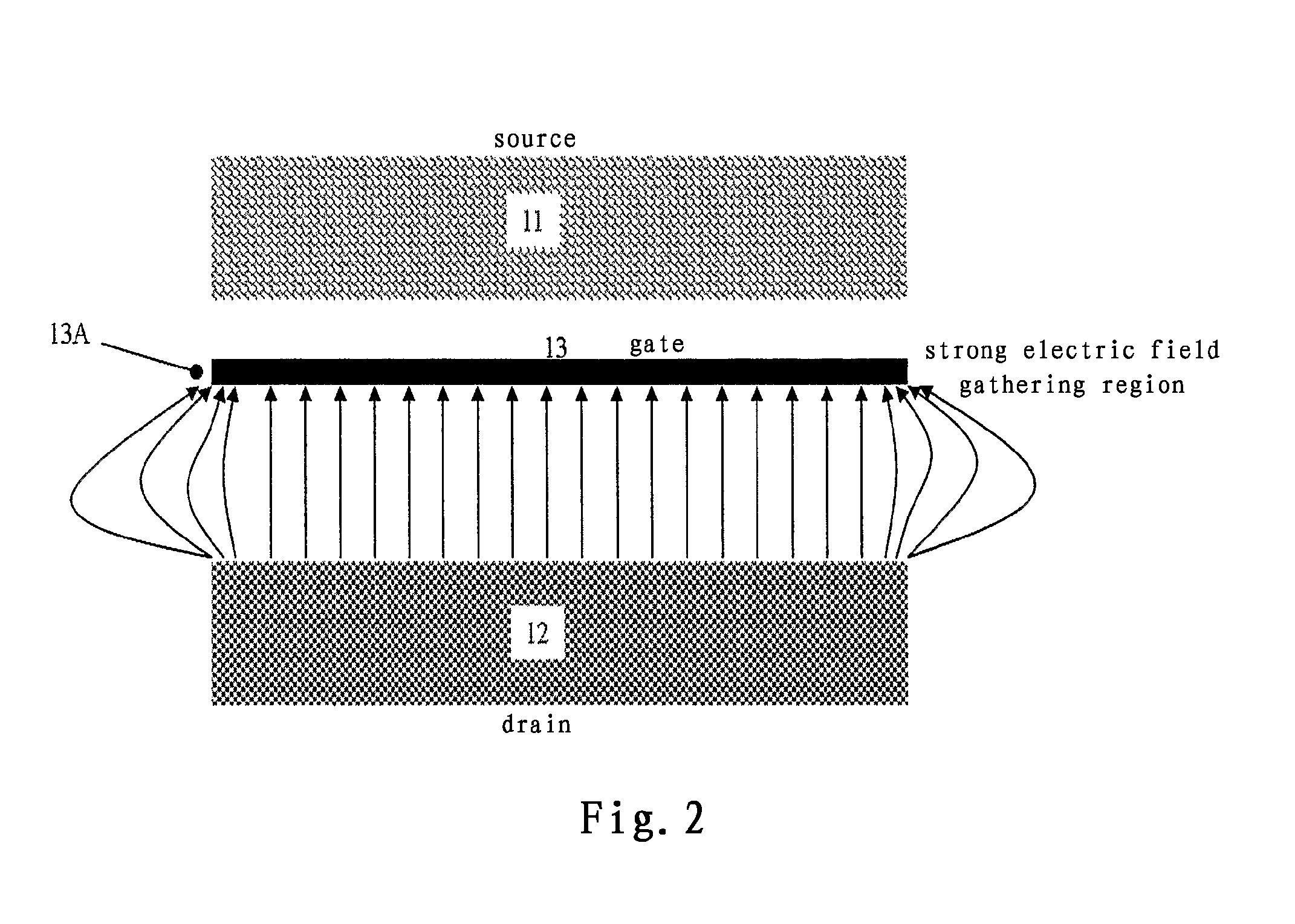
[0030]FIG. 3A depicts layout structure of a semiconductor device according to the embodiment of the invention, FIG. 3B is an enlarged view of one finger of the drain and the gate at corresponding position in FIG. 3A, and FIG. 4 depicts a cross-section view along line A-A in layout structure of the semiconductor device of FIG. 3A.

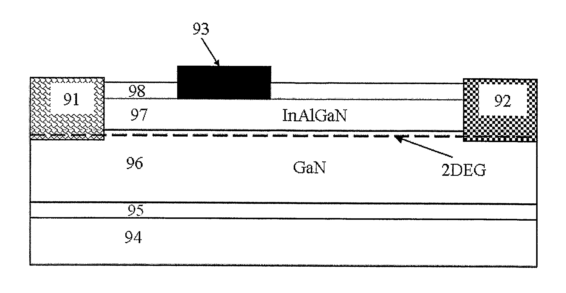
[0031]Next, basic structure of an enhancement mode GaN HEMT of the embodiment as an example of semiconductor device will first be described with reference to FIG. 4

[0032]As shown in FIG. 4, under layer is a substrate 54 for growing GaN material, which generally is Sapphire, SiC, GaN, Si or any other substrates known in the art suitable for growing GaN material, and the invention has no limitation on this.

[0033]On the substrate 54 is an optional nucleation layer 55 for growing a semiconductor layer thereon. It should be appreciated that, instead of forming the nucleation layer 55, a semiconductor layer may also be directly formed on the substrate 54.

[0034]On ...

embodiment 2

[0047]FIG. 5 depicts a layout structure of a semiconductor device according to another embodiment of the invention.

[0048]As shown in FIG. 5, this embodiment is the same as the embodiment 1 shown in the above FIG. 3A in that, the source 41 and the drain 42 comprise intersected multiple fingers 41A, 42B, and the gate 43 is located between the source 41 and the drain 42, and forms a closed ring structure encircling the multiple fingers 41A of the source 41 and the multiple fingers 42B of the drain 42. Description of portions of embodiment 2 that are same as that of embodiment 1 will be omitted herein, and emphasis will be put on difference of the two.

[0049]Embodiment 2 differs from embodiment 1 in two points. First, the gate 43 with closed ring structure entirely encircles the source 41, and the drain 42 is located at peripheral of the gate 43. Second, starting and ending point of the gate 43 are not directly connected, instead, they are connected through an interconnection line 48, wh...

embodiment 3

[0052]FIG. 6 depicts a layout structure of a semiconductor device according to another embodiment of the invention.

[0053]As shown in FIG. 6, this embodiment is the same as the embodiment 2 shown in the above FIG. 5 in that, the source 41 and the drain 42 comprise intersected multiple fingers 41A, 42B, and the gate 43 is located between the source 41 and the drain 42, and forms a closed ring structure encircling the multiple fingers 41A of the source 41 and the multiple fingers 42B of the drain 42, and starting point and ending point of the gate 43 are not directly connected, rather, they are connected through an interconnection line. Description of portions of embodiment 3 that are same as that of embodiment 2 will be omitted herein, and emphasis will be put on difference of the two.

[0054]Embodiment 3 differs from embodiment 2 in that the gate 43 entirely encircles the drain 42, and the source 41 is located at peripheral of the gate 43.

[0055]In this embodiment, a sharp right angle 4...


PUM


Abstract

The invention relates to a semiconductor device and a fabrication method thereof. A semiconductor device according to an aspect of the invention comprising: a semiconductor layer on a substrate; an isolation layer on the semiconductor layer; a source and a drain which are in contact with the semiconductor layer, each of the source and the drain comprises multiple fingers, and the multiple fingers of the source intersect the multiple fingers of the drain; and a gate on the isolation layer, the gate is located between the source and the drain and comprises a closed ring structure which encircles the multiple fingers of the source and the drain.

Description

TECHNICAL FIELD[0001]The present invention relates to a group-III nitride semiconductor device and a fabrication method thereof, in particular, to a novel layout design scheme which facilitates to improve breakdown voltage of a group-III nitride semiconductor device while effectively utilizing device space on a wafer and is particularly suitable to high voltage and large current device.DESCRIPTION OF THE RELATED ART[0002]The dielectric breakdown voltage of third-generation semiconductor Gallium Nitride (GaN) is as high as 3 MV / cm, much higher than that of first-generation semiconductor Silicon (Si) or second-generation semiconductor Gallium Arsenide (GaAs), and thus a GaN electronic device can withstand a very high voltage. Meanwhile, GaN may form a heterojunction structure with other Ga-type compound semiconductor (group-III nitride semiconductor). Since group-III nitride semiconductor has very strong spontaneous and piezoelectric polarization effect, a two-dimensional electron gas...

Claims


Application Information

Patent Timeline
Patent Type & Authority Applications(United States)
IPC IPC(8): H01L29/778H01L21/335
CPCH01L29/7786H01L29/41758H01L29/2003H01L29/4238H01L29/42316
Inventor ZHANG, NAIQIAN
Owner GPOWER SEMICON
Why Eureka
Try Eureka