
Systems and methods for separating condensable vapors from light gases or liquids by recruperative cryogenic processes

a cryogenic process and condensable vapor technology, applied in separation processes, liquefaction, lighting and heating apparatus, etc., can solve the problems of system efficiencies that greatly exceed conventional methods, and achieve the effect of efficient recovery of energy used

Active Publication Date: 2012-11-29
U S BANK TRUST CO NAT ASSOC
View PDF13 Cites 17 Cited by
  • Summary
  • Abstract
  • Description
  • Claims
  • Application Information

AI Technical Summary

Benefits of technology

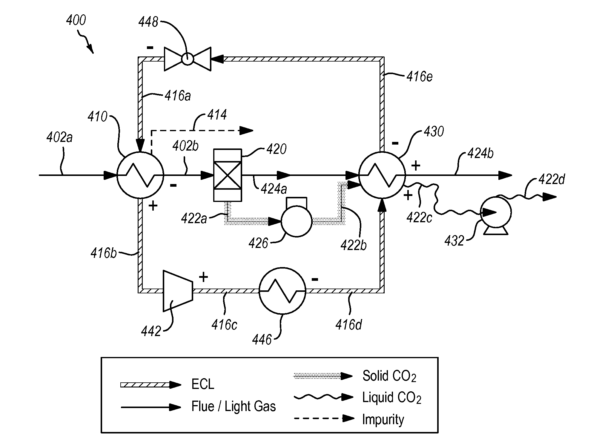
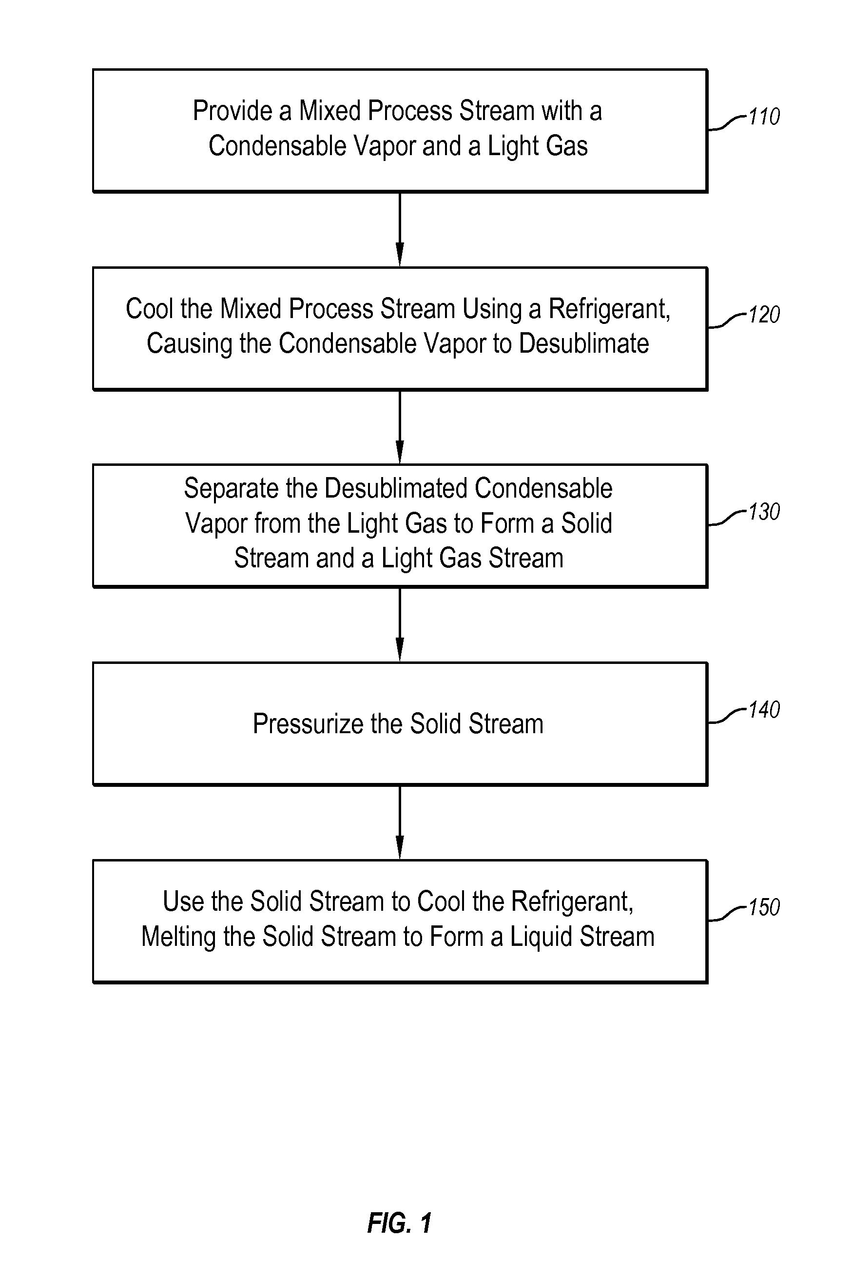
[0009]The present disclosure describes systems and methods for separating condensable vapors (e.g., carbon dioxide) from other gases (e.g., nitrogen) in a continuous separation process. The separation occurs in a cryogenic process using one or more external cooling loops (ECLs) that first cool down a mixed process stream containing condensable vapors and light gases or liquids, causing the condensable vapors to desublimate and form solids. Next, the solids are separated from the light gases or liquids, forming a solid stream and a light gas or liquid stream. Then the refrigerants of the ECL cool by warming the separated solid stream and light gas or liquid stream, efficiently recovering energy used in cooling and desublimating the condensable vapors. Finally the condensed vapors are processed and prepared for transport and ultimate sequestration as the liquid stream warms to a near-ambient temperature. Although the mixed process stream may be compressed in the method, it is not necessary to do so, which affords flexibility of refrigerant choice and eliminating problems associated with compressed acidic process streams and solids formation in expansion devices in a high pressure systems.
[0010]The invention fundamentally differs from conventional cryogenic processes in that instead of only cooling the process stream as in conventional methods, the methods of the invention first cool a process stream, then rewarm it to its original temperature, cooling the refrigerants and recuperating the cooling energy. Furthermore, in some embodiments the methods of the invention stage the cooling and warming of the refrigerants such that the refrigerants of the ECLs and process stream components match in their temperature profiles, in that the temperature differences between the cooler streams and the warmer streams are relatively small and constant, and that the phase changes of the cooler streams are within degrees below the phase changes of the warmer streams. These characteristics of the system maximize the efficiency of heat exchange, leading to system efficiencies that greatly exceed conventional methods.
[0011]As a result, implementations of the invention enjoy all or a portion of the following advantages over conventional separation methods. The systems (1) minimize energy consumption compared to currently contemplated air-separation-unit-based systems (oxyfuel and gasification) and solvent-based systems (traditional absorption) by recovering heating / cooling energy in heat exchangers operating on the input and product streams and by avoiding cyclic process elements that experience temperature changes but are not discharged from the process, leading to energy consumption via entropy generation; (2) minimize energy consumption associated with pressurizing the CO2 by providing the CO2 in condensed form and hence greatly reducing pressurization energy requirements; (3) operate continuously without significant compression, expansion, or other pressure-changing actions on the process gas or process fluid except to provide relatively small pressure increases to maintain flows; (4) allow the primary cooling load to occur in a dedicated, sealed refrigeration circuit that can be separately operated and maintained; (5) provide constant removal of condensate as a condensed phase, avoiding handling and pressurization complexities associated with gas compression; (6) minimize expense by providing a minimally invasive, bolt-on option for removing light gases or liquids, by increasing the minimum temperature that must be achieved relative to air-separation-unit-based systems, and by operating at warmer conditions with broader materials availabilities compared to air-separation-unit-based systems; (7) maximize product purity by forming a solid product phase that is nominally pure; (8) minimize water demand by recovering large fractions of the water in the process gas in a usable form, by decreasing energy consumption and waste heat generation, and by producing a cool light gas or liquid stream useful for cooling other plant processes.
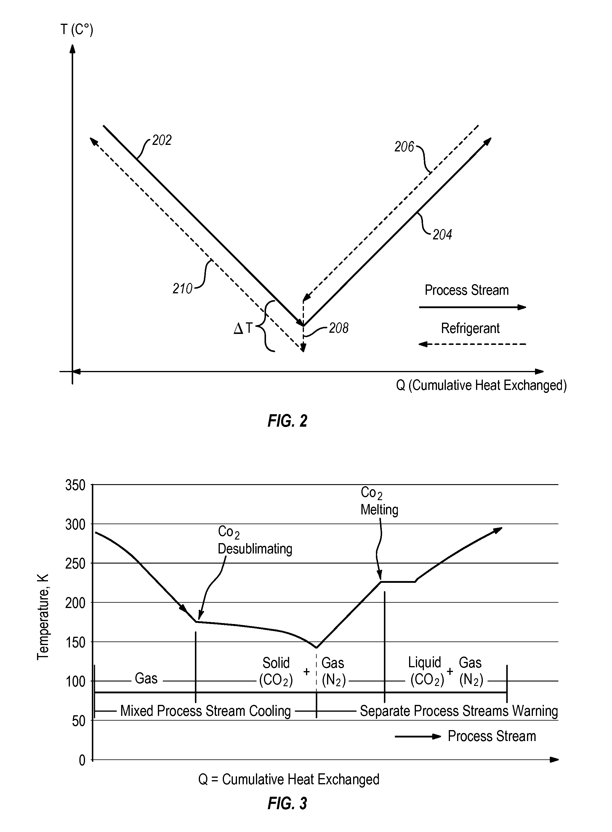
[0013]An embodiment of the invention further improves energy efficiency by matching the temperature profiles between the condensable vapor and the refrigerant, such that the temperature difference between the two remains relatively small, preferably less than 20° C., more preferably less than 5° C., and more preferably still less than 1° C., and the phase changes of one approximate those of the other.
[0017]To maximize heat exchange efficiency, it is advantageous to match the temperature profiles of the cooler streams and the warmer streams in heat exchangers. This can be achieved by choosing and combining different refrigerants, staging multiple heat exchangers, controlling flow rates of the streams, adjusting pressures of the refrigerants, and similar process control and refrigeration operations common to the industry. In some embodiments, a relatively small temperature difference exists between the heat exchanging streams, preferably less than 20° C., more preferably less than 5° C., and most preferably less than 1° C. Energy efficiency can be further improved by bringing the phase change temperatures of the warmer stream and cooler stream into close proximity. For instance, a refrigerant of the inner ECL can be configured to evaporate under a lower pressure in a temperature range of 0-20° C. below the lowest desublimating temperature of the condensable vapor, while the same refrigerant is configured to condense under a higher pressure in a temperature range of 0-20° C. above the melting temperature of the condensable vapor.

Problems solved by technology

These characteristics of the system maximize the efficiency of heat exchange, leading to system efficiencies that greatly exceed conventional methods.

Method used


Image

  • Systems and methods for separating condensable vapors from light gases or liquids by recruperative cryogenic processes
  • Systems and methods for separating condensable vapors from light gases or liquids by recruperative cryogenic processes
  • Systems and methods for separating condensable vapors from light gases or liquids by recruperative cryogenic processes

Examples


example 1

[0122]Example 1 shows the merit of two cryogenic carbon capture processes implemented according to the invention such that it is configured as the double-ECL system shown in FIG. 6 and with an UHE analogous to that shown in FIG. 5. One of the processes is implemented with a simple assumption that the process stream contains N2, O2, and CO2; the other is under a complex assumption that the process stream further contains S, N, Hg, and Cl impurities. The systems also meet the general equipment requirements as stated above.

[0123]Table 1 below summarizes all essential stream conditions and figures of merit. The major equipment energy requirements also appear in Table 1. One of the notable advantages of the invention is that it operates at temperatures considerably warmer than air separation units and therefore enjoys a much broader choice of materials since most common materials of construction are appropriate in the cryogenic carbon capture conditions but many become too brittle or oth...

example 2

[0124]Example 2 uses both laboratory experiments and simulations to determine carbon capture efficiency as a function of temperature in a system implemented according to the invention. Example 2 also shows the energy consumptions as functions of capture efficiency and compression efficiency.

[0125]The systems are implemented with configuration similar to those in Example 1. Repeated laboratory experimental measurements using both simulated and actual coal process gas and using both simulated gas expansion devices (gas expansion through nozzle with external cooling) and refrigerant expansion devices have demonstrated capture efficiencies as shown in FIG. 9, where the discrete data points show empirical data and the solid line represents model prediction matching the empirical data.

[0126]FIG. 10 summarizes the specific energy consumption as functions of capture efficiency and compression efficiency—two prominent parameters, assuming an average 10° C. temperature difference in the heat ...

example 3

[0130]Example 3 shows simulated energy demand data for various embodiments of the invention applied to CCC under different assumptions and parameters, the systems having similar configuration as those in Example 1 and 2.

[0131]Extremely high capture efficiencies require far more energy than theoretical analyses suggest. Indeed, while the theoretical energy costs of perfect separation (100% capture and 100% pure) are finite; there is no continuous industrial process that can achieve this limit with finite energy. The CCC process, however, does not incur rapidly increasing energy costs until close to this limit, as shown in FIG. 10. The entire CO2 flow can only be captured by this technique by going to absolute zero, where vapor pressures are zero but which requires infinite energy. However, temperatures of −130° C. represents greater than 99% capture of an initial 14% flow. The results from these more detailed analyses appear below.

[0132]Table 2 is a compilation of the various process...


PUM


Abstract

Methods and systems of the current invention separate condensable vapors such as carbon dioxide from light gases or liquids in a mixed process stream. The separation is carried out in a cryogenic process using one or more external cooling loops (ECLs) that first cool down a mixed process stream containing condensable vapors and light gases or liquids, causing the condensable vapors to desublimate and form solids. Next, the solids are separated from the light gases or liquids, forming a solid stream and a light gas or liquid stream. Then the refrigerants of the ECL are cooled by warming the separated solid stream and light gas or liquid stream, efficiently recovering energy used in cooling and desublimating the condensable vapors.

Description

CROSS REFERENCE TO RELATED APPLICATIONS[0001]The present application is a continuation of International PCT Application PCT / US12 / 39775 filed May 26, 2012, titled “Systems and Methods for Separating Condensable Vapors from Light Gases or Liquids by Recuperative Cryogenic Processes,” and also claims the benefit of Untied States Provisional Patent Application Ser. No. 61 / 519,667, filed May 26, 2011, titled “Cryogenic Carbon Capture Process,” which are hereby incorporated herein by reference.BACKGROUND[0002]1. The Field of the Invention[0003]The present invention relates to cryogenic systems and methods for separating condensable vapors (e.g., carbon dioxide) from light gases or liquids (e.g., nitrogen gas) by cooling the condensable vapors with one or more external cooling loops to cause the vapors to desublimate.[0004]2. The Related Technology[0005]The separation of carbon dioxide from other light gases or liquids such as nitrogen or methane is important for achieving carbon dioxide s...

Claims


Application Information

Patent Timeline
IPC IPC(8): F25J3/08
CPCB01D53/343Y02C10/12B01D2257/504B01D53/002F25J3/067F25J2205/20F25J2210/70F25J2215/04F25J2220/82F25J2220/84F25J2235/80F25J2270/12F25J2270/42F25J2270/58F25J2270/60B01D2256/10Y02C20/40
Inventor BAXTER, LARRY L.BENCE, CHRISTOPHER S.
Owner U S BANK TRUST CO NAT ASSOC
Learn More