Battery-cell converter systems

a converter system and battery technology, applied in the field of battery converter systems, can solve the problems of battery cell damage, battery cell rapid death, battery damage, etc., and achieve the effects of less charge, higher current output, and higher voltage outpu

Inactive Publication Date: 2013-02-14
TSE LAWRENCE TZE LEUNG
View PDF5 Cites 71 Cited by
  • Summary
  • Abstract
  • Description
  • Claims
  • Application Information

AI Technical Summary

Benefits of technology

[0018]The BCC system can be configured by the monitor and control modules or a main control unit to manage the mismatch among the energy storage devices. For example, the BCC system can be configured to draw less charge from a weaker energy storage device than a stronger energy storage device. Consequently, the BCC system can manage and equate the ageing of the energy storage devices. The BCC system can be configured to disconnect a defective energy storage device from the BCC system so that the rest of the energy storage devices can continue to operate. In another embodiment, the BCC system can be configured to cause a weaker energy storage device connected to said one or more inputs of said one or more DC / DC converters for a shorter period than a stronger energy storage device. The battery-cell converter units can be stacked in series to provide a higher voltage output. The battery-cell converter units can be connected in parallel to provide a higher current output. Furthermore, the series-stacked battery-cell converter units can be connected in parallel to provide higher voltage and current output.

Problems solved by technology

At this moment, high-capacity multi-cell rechargeable battery packs used in handheld appliances, computers, power tools, etc., are rather expensive.
A battery cell can be damaged by being excessively charged to a high voltage or excessively discharged to a low voltage.
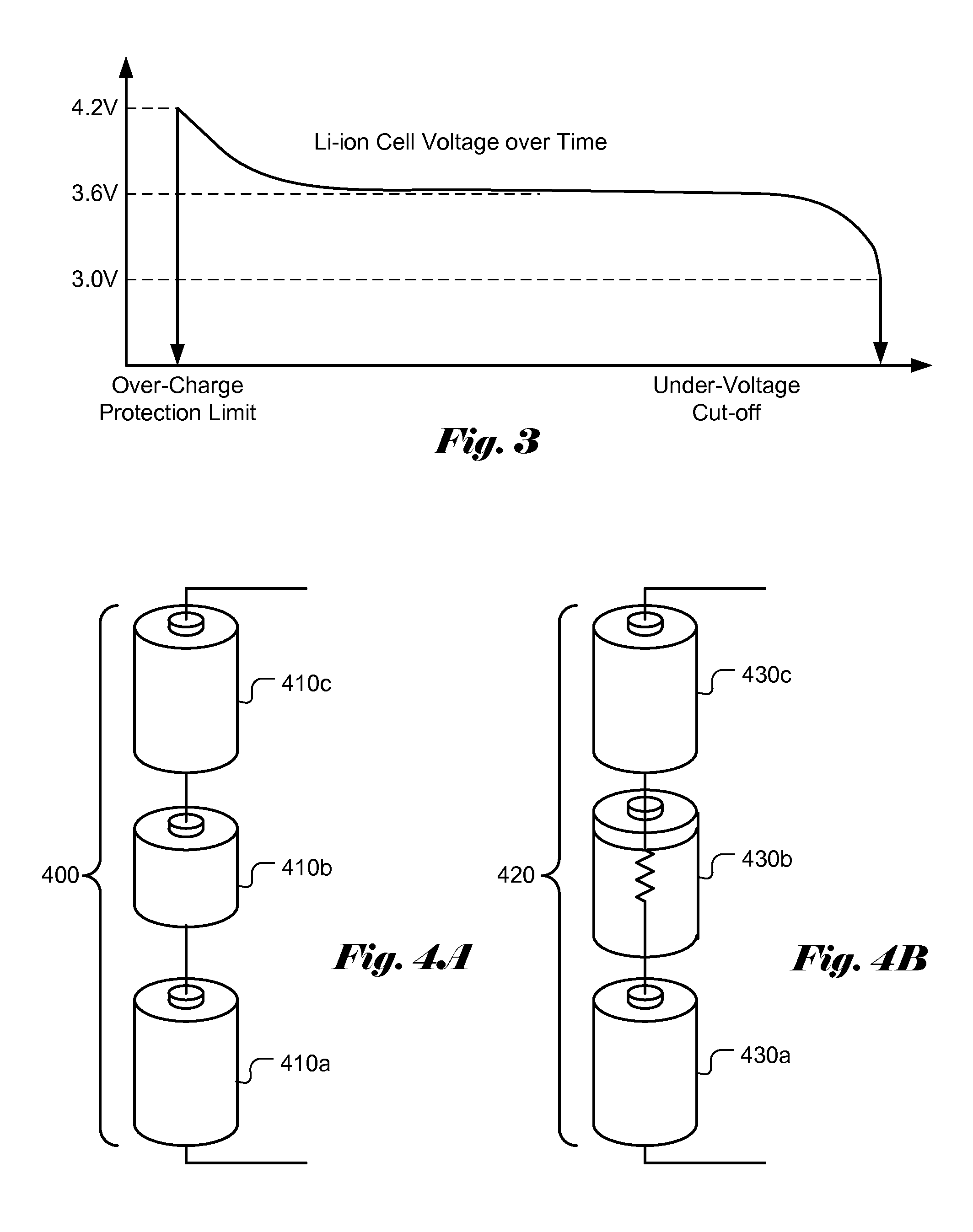
After the battery discharges to about 2.7-3.0V, the battery quickly dies out and may be damaged.
Battery over-charge and over-discharge may reduce battery capacity and battery lifetime, and may even cause hazardous conditions such as fires and explosions.
One of the key challenges in charging / discharging a string of series-stacked multi-cell battery units is related to the non-uniformity of battery cells within the pack due to manufacturing tolerances.
State-of-charge mismatch is a more common issue in rechargeable batteries and the problem occurs when initially equal-capacity cells gradually diverge to contain different amounts of charges.
A weakest battery cell tends to limit the overall capacity of the entire battery pack unit.
Factories that do not adopt the binning process may result in low battery yield on their battery cells.
Besides, the out-of-spec cells will be rejected and disposal of the out-of-spec cells will increase environment pollution.
However, such process increases manufacturing cost.
It is apparent that this binning step is a brute-force approach and can only partially mitigate the cell mismatch issue since cell mismatches tend to get worse after multiple charge / discharge cycles.
Also, mismatches may result from different cell temperatures in the operating environment.
As a result, mismatch degradations occur more often after battery cells are manufactured and therefore cannot be easily addressed during battery cell manufacturing and quality control.
When cell 450b is severely degraded, it causes the whole battery cell pack 440 to fail.
However, it becomes a complex task for a series string of battery cells when the cells are not well-matched.
Since the cells often are not identical, mismatches among cells exist.
In practice, battery cell balancing via charge transfer is typically limited to charge transfer to a neighboring cell.
It is impractical to implement a matrix of charge transfer circuits that would provide a charge transfer path to any two cells.
In addition, there are losses associated with charge balancing or charge transferring between cells.
As an individual cell becomes defective such as open circuited, the whole chain of series-stacked cells cannot be used and the multi-cell battery unit capacity is immediately halved.
Consequently, the conventional way of load connection to the battery pack imposes a harsh requirement for the load to withstand a large operating voltage range.
Therefore, the direct connection to the string of series-stacked cells not only makes the design of the associated electronic circuits very challenging, but also requires those circuits to be over designed to accommodate the large variations in the input voltage.
The need to operate under a large voltage range also creates system inefficiencies, waste energy and increase system cost.
In other applications with large arrays of cells such as electrical vehicles (EVs), the series-stacked topology creates even more undesirable characteristics.
If one of the cells in the series of cells ages faster than others or prematurely dies, the entire series-stacked string's capacity will be limited by the weakest cell or the entire string may become malfunction.
The overly designed redundancy adds more cost, space, and weight, etc.
Since managing cell matching is such a critical practice for maximizing pack capacity and pack life, sophisticated and expensive cooling system is often used in EV battery system to ensure cell temperatures are within 1 to 2 degree Celsius so that the cells can have as similar aging rates as possible (cell aging rate is a function of temperature).
Another key disadvantage of conventional battery system is that the output voltage drops as cells are discharged as mentioned earlier.
Again, such requirement adds additional cost, space and weight, etc.
This causes the output voltage of the pack to drop.
This characteristic imposes additional system design challenges on the electrical motor system, which again translates into higher system cost in order to circumvent this voltage drop issue during EV acceleration.

Method used


Image

  • Battery-cell converter systems
  • Battery-cell converter systems
  • Battery-cell converter systems

Examples


Embodiment Construction

[0039]As mentioned earlier, various types of cell mismatches exist among battery cells. When multiple battery cells with mismatches are used to create a battery pack, the weakest battery cell often determines the usability and life time of the battery pack. Therefore, the present invention eliminates the requirement of tightly matched cells within the battery pack while providing a regulated, managed output to the subsequent electrical loads. There are several main differences between a system incorporating an embodiment of the present invention and a convention system. One main difference is that there is no need to transfer charges from one battery cell to another in the system incorporating an embodiment of the present invention. While convention system stacks up battery cells to achieve a higher voltage output, a system incorporating an embodiment of the present invention achieve a higher voltage output by either using a DC / DC boost converter to boost the voltage of the energy s...


PUM


Abstract

A battery-cell converter (BCC) management system is disclosed. The BCC system comprises one or more battery-cell converter units that are configured to provide regulated main power output from the outputs of DC / DC converters inside the battery-cell converter units. Each battery-cell converter unit comprises an electrical energy storage cell bank, one or more DC / DC converters, one or more electrical connection devices and a monitor and control module coupled to other components of the battery-cell converter unit. Multiple battery-cell converter units can be stacked in series to increase output voltage. In another embodiment, multiple battery-cell converter units can be connected in parallel to increase output current. Accordingly, the BCC management system disclosed improves battery pack usage efficiencies, increase battery pack useable time per charge, extend battery pack life-time as well as lower battery pack manufacturing cost.

Description

CROSS REFERENCE TO RELATED APPLICATIONS[0001]The present invention is continuation-in-part of and claims priority to U.S. Non-Provisional patent application, Ser. No. 12 / 709,459 filed on Feb. 2, 2010, entitled “Battery-Cell Converter Management Systems”, which claims priority to U.S. Provisional Patent Application, Ser. No. 61 / 208,304, filed on Feb. 23, 2009, entitled “Multi-cell battery management systems”. The U.S. Non-Provisional Patent Application and U.S. Provisional Patent Application are hereby incorporated by reference in their entireties.FIELD OF THE INVENTION[0002]The present invention generally relates to systems and methods of constructing a battery unit out of a plurality of battery cells coupled to or integrated with a plurality of voltage / current converter units for wear-leveling (equalizing ageing) of rechargeable batteries in a multi-cell battery system.DESCRIPTION OF RELATED ART[0003]With the growing requirements of high-energy battery-operated applications, the de...

Claims


Application Information

Patent Timeline
Patent Type & Authority Applications(United States)
IPC IPC(8): H02J7/00
CPCG01R31/3658G01R31/40H02M3/158Y02T10/7055H02J7/0013H02J7/0014H02M3/1584G01R31/396Y02T10/70
Inventor TSE, LAWRENCE TZE-LEUNG
Owner TSE LAWRENCE TZE LEUNG
Why Eureka
Try Eureka