Neutron detector and method of making

a neutron detector and detector technology, applied in the field of neutron detectors, can solve the problems of limiting the potential sensitivity of these detectors, he-3 being uneconomical for many neutron detection applications, and the former normally has a substantially lower neutron detection sensitivity, so as to reduce voltage and power requirements, reduce the effect of neutron discrimination

Inactive Publication Date: 2013-03-21
MATERIALS INNOVATION INC
View PDF3 Cites 16 Cited by
  • Summary
  • Abstract
  • Description
  • Claims
  • Application Information

AI Technical Summary

Benefits of technology

[0024]Objects of the present invention include the following: providing a more efficient (sensitive) neutron detector, both on an absolute and a per-volume basis; providing a neutron detector that more effectively discriminates neutrons from other types of ionizing radiation; providing a gas-filled neutron detector with improved signal characteristics; providing a gas-filled neutron detector with reduced voltage and power requirements; providing a gas-filled neutron detector that is easier and less expensive to manufacture; providing a gas-filled neutron detector of enhanced field-ruggedness; providing a gas-filled neutron detector that can be filled with multiple types of gases; and providing a gas-filled neutron detector that can be formed into many different shapes and sizes. These and other objects and advantages of the invention will become apparent from consideration of the foll

Problems solved by technology

BF3 detectors present major drawbacks compared to He-3 detectors, including the toxicity of the gas, and a commonly recognized limitation of the pressure for effective operation of the detector, which limits the potential sensitivity of these detectors, compared to conventional counters that can be filled with 10 or 20 atmospheres of He-3.
Neutron detectors based on boron-10 lined tubes have attracted increased attention in recent years because of a supply shortage of He-3 gas and a consequent surge in price, making He-3 uneconomic for many neutron detection applications.
A disadvantage of boron-lined tubes compared to detector tubes containing helium-3 or boron trifluoride is that the former normally has a substantially lower neutron detection sensitivity than the latter due to the self-shielding of boron-10 neutron capture reaction products by the solid coating containing the boron (other solids also experience this effect).
Drawbacks to using smaller diameter tubes include greater difficulty in coating the inside surface of the tubes with boron or other neutron-reactive material and in inserting a thin anode wire into the tube, particularly if the tube is small (e.g. Proportional Technologies' straw tubes are 4 mm in diameter and can be up to six feet long).
Although the companies mentioned have developed engineering solutions for manufacturing these detectors, it remains the case that the smaller the tube diameter, the greater the number of tubes required to provide a performance-equivalent replacement for a He-3 tube detector of a given size, resulting in an obvious cost increase.
On the other hand, boron coated straw neutron detectors normally use a central anode wire just as boron-lined neutron counters do, and this approach does not simplify the difficult task of sliding the wire into the straw.
In the disclosed detector configuration, McGregor et al. indicate how two

Method used


Image

  • Neutron detector and method of making
  • Neutron detector and method of making
  • Neutron detector and method of making

Examples


example 1

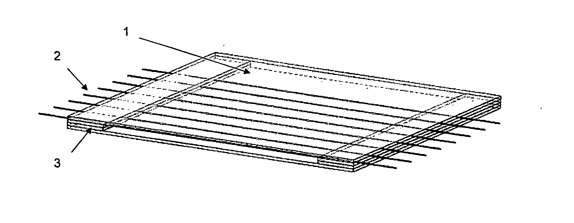
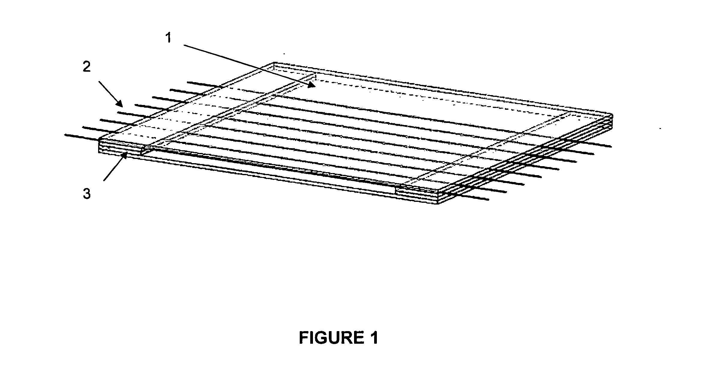
[0094]Flat Stacked Detector: A 35 cm long, 5 cm wide, copper sheet of 50 micrometers thickness was coated with boron layer on both sides. The boron layer consisted of B4C enriched with 96% B-10 with an average areal density of 0.14 mg / cm2. A set of Teflon sheets 0.5 mm thick×5.5 cm long×3.5 cm wide, were cut with four windows of 1.9 cm on a side, as shown in FIG. 7. Two Teflon sheets were applied against the copper sheet such that the Teflon sheets were centered on the width of the copper sheet. A 25 μm diameter conductive wire was woven around the two Teflon sheets such that the wire did not touch the copper sheet as shown in FIG. 8. A second set of Teflon sheets were then applied onto the first set of Teflon sheets such that the wire was sandwiched between two Teflon sheets on each side of the copper sheet. The copper sheet was then folded around the dielectric-anode sandwich once. This process was repeated four more times, creating a 2 cm thick structure comprising five layers of...

example 2

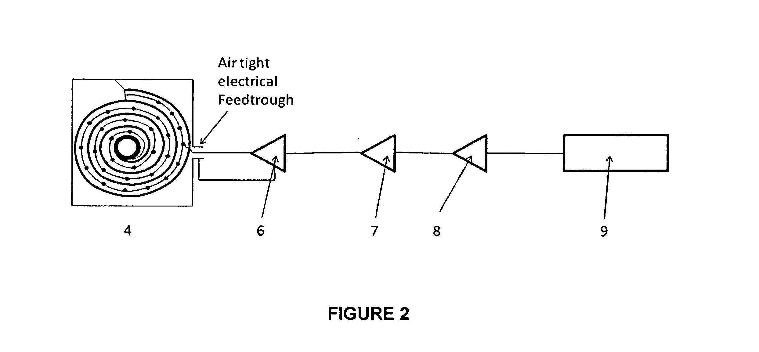
[0096]Cylindrical Detector with Single Copper Sheet in Spiral Configuration: A 0.05 mm thick copper sheet of 63 cm length and 15.2 cm width was coated on both sides with boron carbide isotopically enriched to 96% B-10. The average coating thickness was about 0.5 μm. The coating was applied to the copper sheet in strips of around 12 mm width with around 3 mm separation between the coated strips along the length of the sheet. The last 2.5 cm at one end of the copper sheet and the last 10 cm at the other end were left uncoated, enabling the uncoated portion of the copper sheet to constitute the outer surface of the detector when the detector is closed and sealed. Strips of Teflon 3 mm wide were prepared with adhesive on each side. Two strips 6 mm wide were prepared similarly and V-shaped notches were made on one side every 4 mm. A length of 1.6-cm diameter copper tubing was used as the substrate. The end of the copper sheet was rolled around the copper tube and maintained in place with...

example 3

[0098]Concentric Cylindrical Tubes: In a conceptual design validated by simulation, a central cylinder, having an outer diameter of 12 mm, is coated on its outer surface with a boron layer having a thickness of about 1 micrometer. A ring made of dielectric sheet-like material, having an inside diameter substantially equal to the outer diameter of the copper cylinder, such that it fits around said copper cylinder, and having a thickness of about 0.7 mm and a length of 6 mm is applied at each extremity of the cylinder in such a way that half of its length lies against the copper cylinder, and the other half extends beyond the copper cylinder. The outer edges of the dielectric rings are cut to create a series of notches spaced about every 4 mm and about 1 mm deep. A 0.025 mm conductive wire is woven from one ring to the other, hooking onto each ring via the small notches described above. The distance between each loop of wire is thus about 4 mm. A second set of rings is applied on the ...


PUM

PropertyMeasurementUnit
Fractionaaaaaaaaaa
Thicknessaaaaaaaaaa
Thicknessaaaaaaaaaa

Abstract

A neutron detector comprises at least two conductive cathode sheets lying parallel to one another and coated with neutron reactive material on at least one side thereof; dielectric material separating the cathode sheets and covering less than about 80% of their surface area; and a plurality of anode wires lying generally parallel to the cathode sheets and separated from them by the dielectric, with the distance between adjacent anode wires being no more than twenty times the distance between said cathode sheets. The cathode sheets may be flat or curved; they may be separate plates or they may be successive folds or windings of a single folded or spiral-shaped metal sheet. Related methods for building the detector are disclosed.

Description

CROSS REFERENCE TO RELATED APPLICATION[0001]This application is related to U.S. patent application Ser. No. ______ entitled, Neutron Detector and Method of Making, filed by the present inventors on even date herewith, the entire disclosure of which is incorporated herein by reference.BACKGROUND OF THE INVENTION[0002]1. Field of the Invention[0003]The invention pertains to apparatus and methods for detecting neutrons and more particularly to neutron detectors containing generally parallel or concentric detecting elements made of thin sheet-like material coated with neutron-reactive materials.[0004]2. Description of Related Art[0005]Conventional Neutron Detector Tubes[0006]Tubular helium-3 proportional counters have been the most common type of neutron detector in use for some years, such as described by Bonner in U.S. Pat. No. 3,102,198 and Morgan in U.S. Pat. No. 3,240,971. Boron trifluoride (BF3) gas was originally commonly used for neutron detection and was replaced by He-3 based ...

Claims


Application Information

Patent Timeline
IPC IPC(8): H05K3/10B05D3/12B05D5/00
CPCH01J47/1205Y10T29/49155G01T3/008Y10T29/49126
Inventor STEPHAN, ANDREW C.JARDRET, VINCENT D.
Owner MATERIALS INNOVATION INC
Why Eureka
Try Eureka