Increased Resource Recovery by Inorganic and Organic Reactions and Subsequent Physical Actions that Modify Properties of the Subterranean Formation which Reduces Produced Water Waste and Increases Resource Utilization via Stimulation of Biogenic Methane Generation

a technology of inorganic and organic reactions and subterranean formations, which is applied in the direction of fluid removal, well accessories, chemistry apparatus and processes, etc., can solve the problems of fracturing the surrounding formation, unable to achieve complete radial coverage of the formation, and unable to control the propagation of fractures with increasing distance from the well, etc., to achieve the effect of facilitating the micro accumulation of gas

Active Publication Date: 2013-03-21
PANTANO JOHN
View PDF2 Cites 22 Cited by
  • Summary
  • Abstract
  • Description
  • Claims
  • Application Information

AI Technical Summary

Benefits of technology

[0095]Establishing a new network that facilitates the micro accumulation of gas to migrate to location of accumulation where economic recovery of natural gases later occurs

Problems solved by technology

While this technique is generally useful, complete radial coverage of the formation and a controlled propagation of the fracture with increasing distance from the borehole are not achieved.
The detonation of an explosive device or materials in a borehole to achieve explosive fracturing of the surrounding formation, however, suffers from the same disadvantage noted above with respect to hydraulic fracturing operations; namely, the difficulty of propagating the fracture at increasing distances from the injection borehole.
Explosive fracturing by the detonation of an explosive device in a borehole also requires a subsequent cleanup operation before hydrocarbon recovery can begin, increasing both the time and expense.
Some aluminum in its molten state is projected into the perforation and forced to react with water that also enters the perforation, creating another explosion, fracturing the crushed zone of the perforation and initializing cracks.
This method is limited by the use of molten Al.
Also, the location where the explosion can be set is limited to in or near the borehole.
Moreover, the timing of the explosion is limited to a short period of time after placement.
For instance, the high capillary pressures associated with the use of an aqueous system may restrict the flow of produced gaseous hydrocarbons such as methane.
Capillary pressures of several thousand psi (pounds per square inch) may result in low permeability formations, wherein the high pressure differential needed to initiate gas flow may result in extended fluid recovery times, or permanent loss of effective fracture half length.
However, increasing concentrations of dissolved carbon dioxide in the liquid hydrocarbon make it progressively more difficult to gel with phosphate ester and alkylphosphonic acid ester gel systems.
As a result, there is a limit to the concentration of carbon dioxide that may be present in such servicing fluids.
For instance, if too high a concentration of carbon dioxide is present, the servicing fluid may not have a viscosity sufficient to carry the needed quantity of particulates to a desired location within a wellbore, to adequately control fluid leak off, and to generate the desired fracture geometry.”
Controlled pulse fracturing causes radial fracturing near the wellbore.
However, these methods do not discriminate between the water flowing networks or the hydrocarbon flowing networks.
The production of O2 could also lead to problems in many reservoirs by establishing aerobic biological conditions.
Although this method focuses on changing the orientation of the fracture, it does not address how to prevent preferentially fracturing the water flowing networks.
Water production is a significant problem in maximizing hydrocarbon recovery.
Besides reducing the amount of hydrocarbon recovery, there are tremendous costs and environmental impacts.
Separation and disposal of produced water requires a substantial effort.
Inhibiting the corrosion of equipment is a challenge and creates environmental impacts.
The damage is primarily skin damage caused by drilling, completion and workover fluids and precipitation of deposits from produced water or oil (such as scale).
Since the acidizing fluids do not discriminate between hydrocarbon and water bearing zones, an undesired result may be obtained wherein the production of formation water is increased.
Coating the material and keeping formations at elevated temperatures is expensive and difficult.
These methods do heat the formation, but the changes in the subsurface are only effective close to the wellbore.
This method is limited to conditions where the hydrocarbon liquid will invade those “cleaned out” pores quicker than the surrounding water.
These methods do not benefit from the chemical reactions being triggered out in the formation as hydrocarbon channels become water flow-path channels.
Nor do these methods describe how to get the chemical reactions' byproducts to help change the environment to stimulate biogenic methane production.
They noted that “methanogens keep the partial pressure of hydrogen extremely low and thus allow otherwise thermodynamically unfavorable reactions to occur.”
The methods use heat to raise the temperature of the formation, but the changes of the subsurface are only effective close to the wellbore.
This method is limited to having solutions injected into the subsurface and does not dynamically change the subsurface conditions.
The utilization of the byproducts of the reactions deeper into the formation is less efficient and effective due to the location of the reactions.
There are disadvantages, both economic and environmental, with respect to current methodologies.
Current processes fail to generate the greatest recovery of hydrocarbons (and thereby optimize economic return) from the fracturing process due to the fact that current chemicals / processes only create pressure and fractures near the wellbore, and less so farther away from the wellbore.
This failure results in the abandonment of hydrocarbons outside the reach of the current fracture length.
Current practices also do not preferentially connect oil ganglions.
There is no procedure for an agent to react farther away from the well, or to create a domino effect by continuing to create new fractures farther away from the wellbore.
Instead, currently, water-bearing networks, along with oil- and gas-networks, are all indiscriminately opened and propped, which necessarily increases the flow of water into the wellbore.

Method used


Image

  • Increased Resource Recovery by Inorganic and Organic Reactions and Subsequent Physical Actions that Modify Properties of the Subterranean Formation which Reduces Produced Water Waste and Increases Resource Utilization via Stimulation of Biogenic Methane Generation
  • Increased Resource Recovery by Inorganic and Organic Reactions and Subsequent Physical Actions that Modify Properties of the Subterranean Formation which Reduces Produced Water Waste and Increases Resource Utilization via Stimulation of Biogenic Methane Generation
  • Increased Resource Recovery by Inorganic and Organic Reactions and Subsequent Physical Actions that Modify Properties of the Subterranean Formation which Reduces Produced Water Waste and Increases Resource Utilization via Stimulation of Biogenic Methane Generation

Examples


example 1

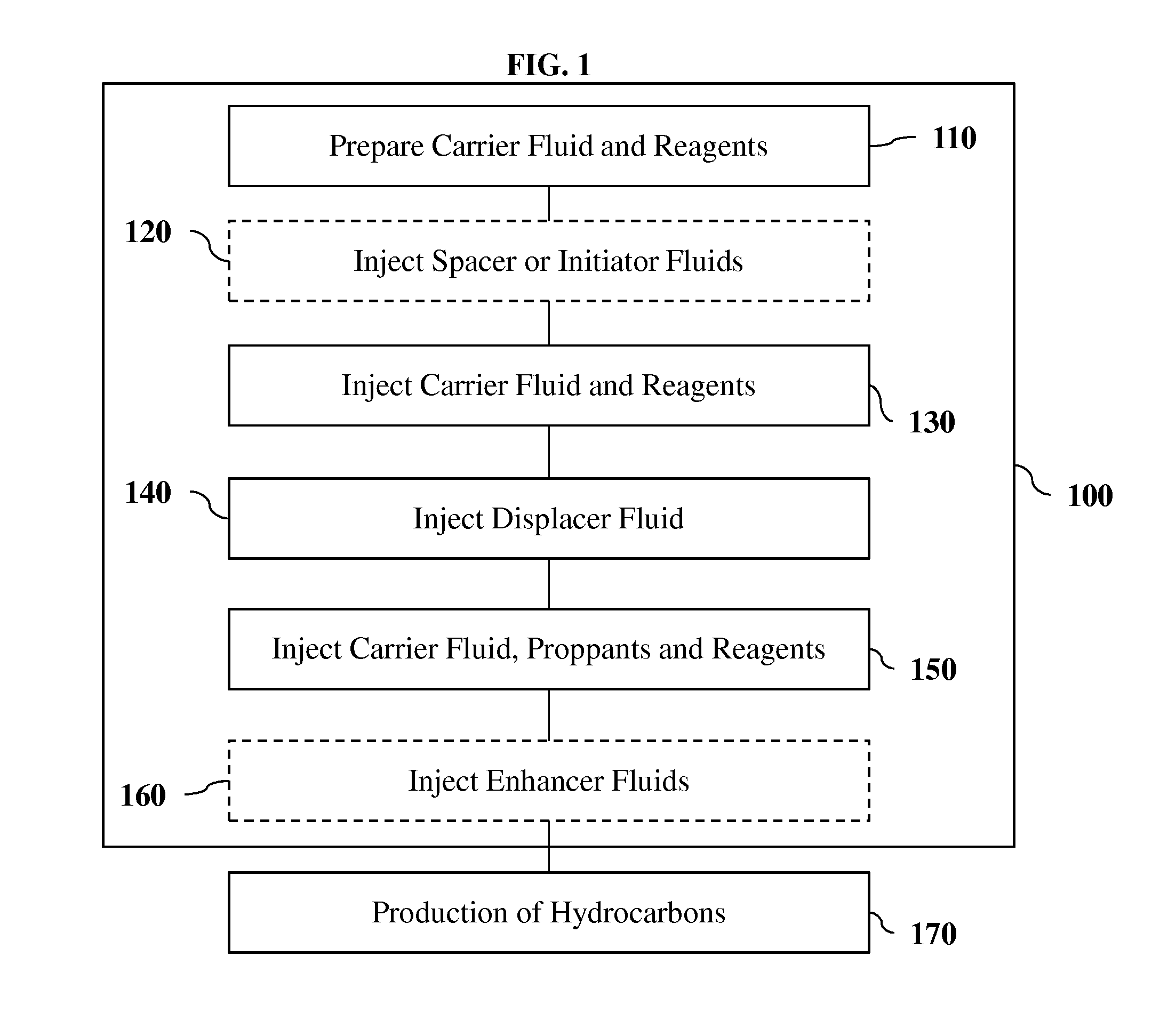
[0117]The block diagram of FIG. 1 illustrates the steps taken to effectively and efficiently recover hydrocarbons from the subsurface using one embodiment, 100. The first step, 110, is at the surface, where a carrier fluid is prepared and the proper amounts of reagents are blended in the carrier fluid.

[0118]The reagents have some of the following attributes: a) reactive with water or a water-based solution; b) produce pressure by either a change in phase and / or the density of the solids produced are less than the density of the reagents, which in turn creates excess pressure; c) produce hydrogen gas; d) produce a water soluble anion that will selectively precipitate solids from interaction with water; e) form a solution that decreases interfacial tension of hydrocarbons which makes hydrocarbons more flowable; f) generate heat and raise both the surrounding fluids and solids temperature; and g) combinations of the above.

[0119]The reagents are preferably comprised of one or more alkal...

example 2

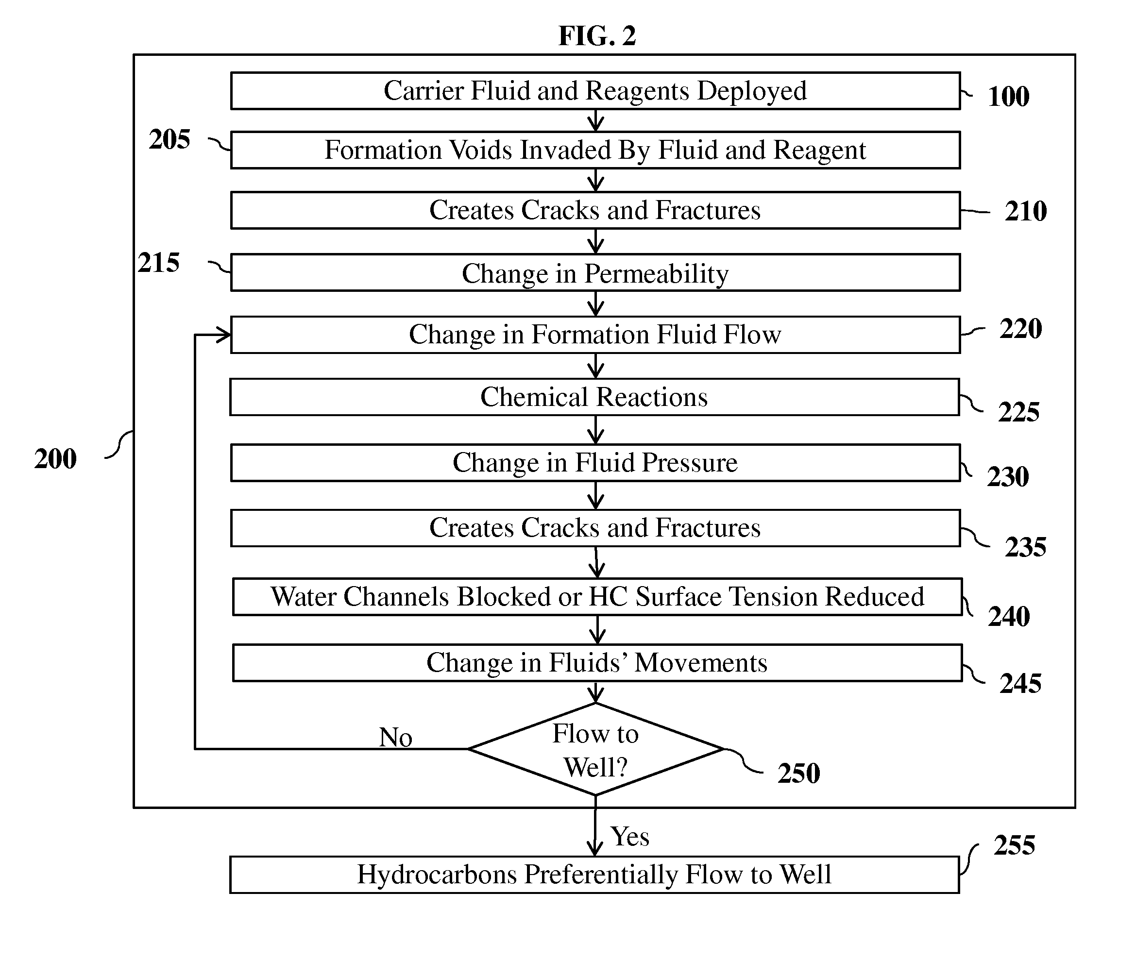
[0128]FIG. 2 depicts the flow chart illustrating one embodiment of the present invention 200. Method 200 starts by applying the steps in 100, deploying carrier fluids and reagents into the subsurface in the proper sequencing, volumes, rates and pressures. One such combination uses sodium metal (Na) as the reagent in liquefied petroleum gas (LPG) as the carrier fluid. Sodium has a density at 25° C. of 0.968 g·cm-3 and at 97.72° C. (melting point) a liquid density of 0.927 g·cm-3. This example describes sodium used as a liquid, although at different pressures and temperatures, sodium might be a solid. In the instance of applying this technique at subterranean conditions above the melting point of sodium, the reagent is in solution with the carrier fluid. For the purpose of brevity, this description will be focused on liquid sodium metal as the reagent, although a multitude of other combinations or reagents and their phase, chemistry and physical attributes are as or more applicable gi...

example 3

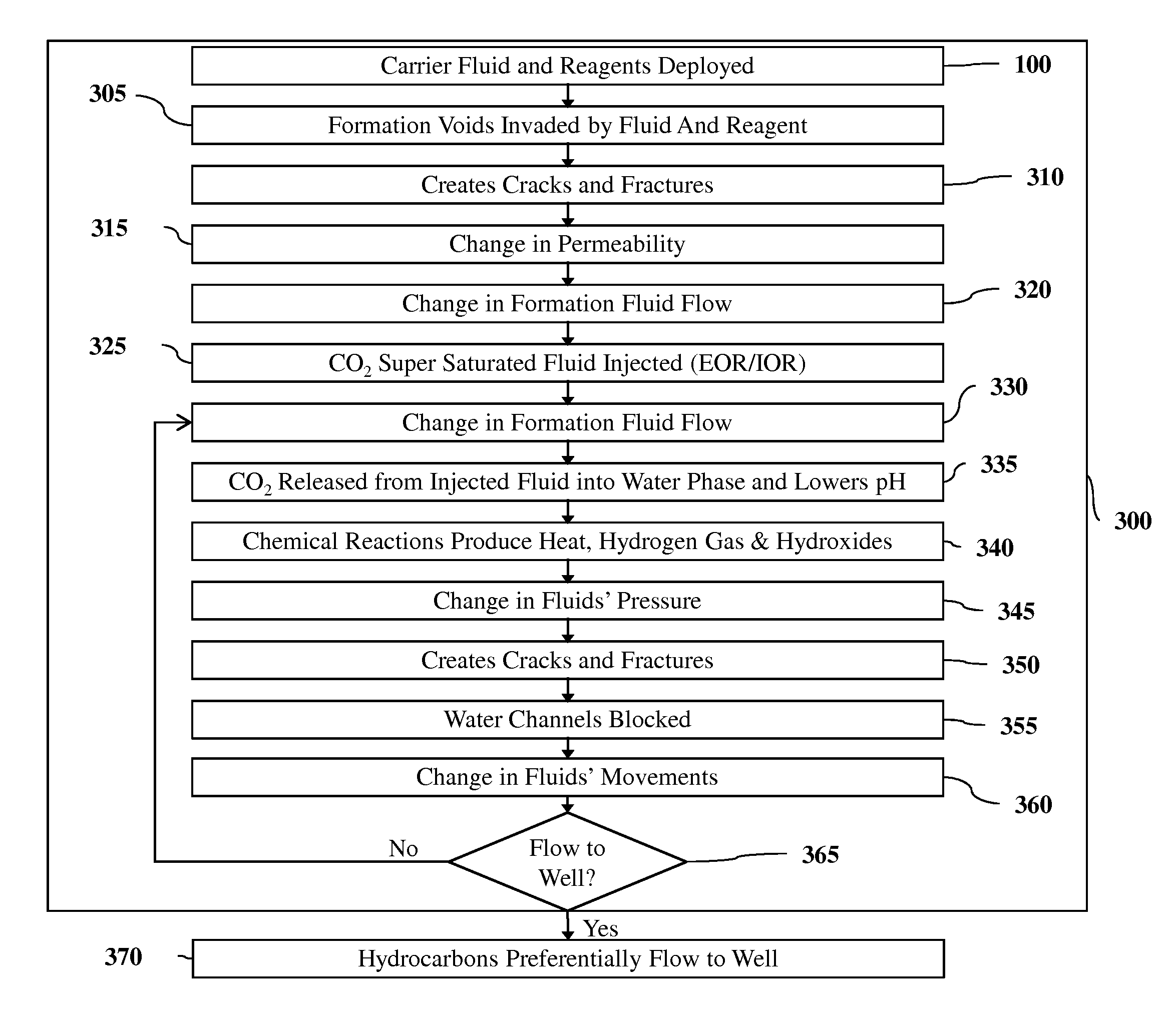
[0138]FIG. 3 depicts the flow chart illustrating one embodiment of the present invention 300. Method 300 starts by applying the steps in 100, which is deploying carrier fluids and reagents into the subsurface in the proper sequencing, volumes, rates and pressures. One such combination uses the alkaline earth magnesium (Mg) as the reagent in a water based carrier fluid that is supersaturated with CO2 gas. Magnesium has a density at 25° C. of 1.74 g·cm-3. The melting point of magnesium is 647° C. Magnesium is therefore a fairly lightweight solid. A multitude of other combinations or reagents and their phase, chemistry and physical attributes are as or more applicable given a set of conditions of the subterranean formation (permeability, capillarity, wettability, phase, composition, mineralogy, temperature, pressures etc.).

[0139]Step 305 is characterized by the voids of the formation being invaded by the carrier fluid and reagent. The fluids that were occupying that space are displaced...


PUM


Abstract

Methods of resource recovery include reagents placed in a subterranean formation. The reagents generate heat, hydrogen gas and alkalinity which changes fluid flow characteristics. The forces of the reactions create fractures and cracks far from the well bore. These cracks and fractures are sealed if water is being transmitted through or near the reactions. As a result, the targeted fluids more efficiently flow to the well, along with decreased amounts of water waste, while stimulating generation of biogenic gases in the subterranean formations.

Description

CROSS-REFERENCE TO RELATED APPLICATIONS[0001]Not ApplicableSTATEMENT REGARDING FEDERALLY SPONSORED RESEARCH OR DEVELOPMENT[0002]Not ApplicableREFERENCE TO SEQUENCE LISTING, A TABLE, OR A COMPUTER PROGRAM LISTING COMPACT DISC APPENDIX[0003]Not ApplicableBACKGROUND OF THE INVENTIONField of Invention[0004]This method relates to the recovery of natural resources from subterranean formations. More specifically, the invention relates to chemicals being delivered to the subsurface for improvement of hydrocarbon or other preferred fluid movement to a well while restricting unwanted water movement and stimulating production of biogenic methane.INTRODUCTION[0005]Recovering hydrocarbons from the subsurface involves many challenges. The dynamics of reactive multiphase fluid flow in porous media are responsible for the complexity. Many factors control the rate of fluid movement. Improvements in conditions for maximum recovery of hydrocarbons rely on changing the pressure difference between the p...

Claims


Application Information

Patent Timeline
Patent Type & Authority Applications(United States)
IPC IPC(8): E21B43/16E21B43/00
CPCE21B43/25C09K8/592E21B43/164E21B43/24E21B43/2405
Inventor PANTANO, JOHN
Owner PANTANO JOHN
Why Eureka
Try Eureka