Method, apparatus and system for electroporation

a cell and apparatus technology, applied in the field of cell apparatus and system for electroporation, can solve the problems of cumbersome arrangement of in-vivo treatment of disease, potentially unsuitable for in-vivo applications, etc., and achieve the effects of high permittivity, high conductivity, and high permittivity

Inactive Publication Date: 2013-05-02
SOIKUM SOIWISA +2
View PDF0 Cites 67 Cited by
  • Summary
  • Abstract
  • Description
  • Claims
  • Application Information

AI Technical Summary

Benefits of technology

[0071]In some embodiments the apparatus may comprise one or more electrodes that are adapted to be implanted within the body of the subject. Suitable electrodes are known in the art as used for conventional electroporation and for irreversible electroporation treatment. In preferred embodiments the electrodes are adapted to provide a field localised in the vicinity of a region of target cells, such as for example a seat of infection or a tumour. In an alternative embodiment the electrodes are adapted to provide a field over a larger region, so as for example to treat a delocalized condition over a region of the subject's body.
[0072]In some embodiments the apparatus comprises means to change the orientation of the applied field during a course of treatment. In some embodiments the apparatus includes means to move one or more electrodes with respect to the subject or vice versa.
[0073]According to a further aspect of the invention there is provided a method of targeted electroporation of a target cell comprising the steps of: causing a particle of high permittivity or high conductivity to associate with the exterior of a target cell membrane and exposing

Problems solved by technology

Raffa et al show an in-vitro example of the effect of CNTs used in this way but this is clearly cumbersome to arrange for in-vivo tre

Method used


Image

  • Method, apparatus and system for electroporation
  • Method, apparatus and system for electroporation
  • Method, apparatus and system for electroporation

Examples


example 1

The Effects of Varying Bead Concentration (2, 0.5 and 0 μl) on Spore Electrolysis Efficiency

[0258]One hundred mg of Biobit Bacillus thuringiensis subsp. kurstaki containing 3.2×10⁹ spores / g (Valent BioSciences Corp, Libertyville, USA) was re-suspended in 1 ml of demineralized water and centrifuged for 90 sec. at 12000 rpm. This procedure was repeated 4 times. The supernatant was discarded. The final solution contains approximately 3.2×10⁸ spores. This solution was diluted to a final concentration of 3.2×10⁵ spores / ml. and subsequently 12 μl spore sample was used for electrolysis and PCR.

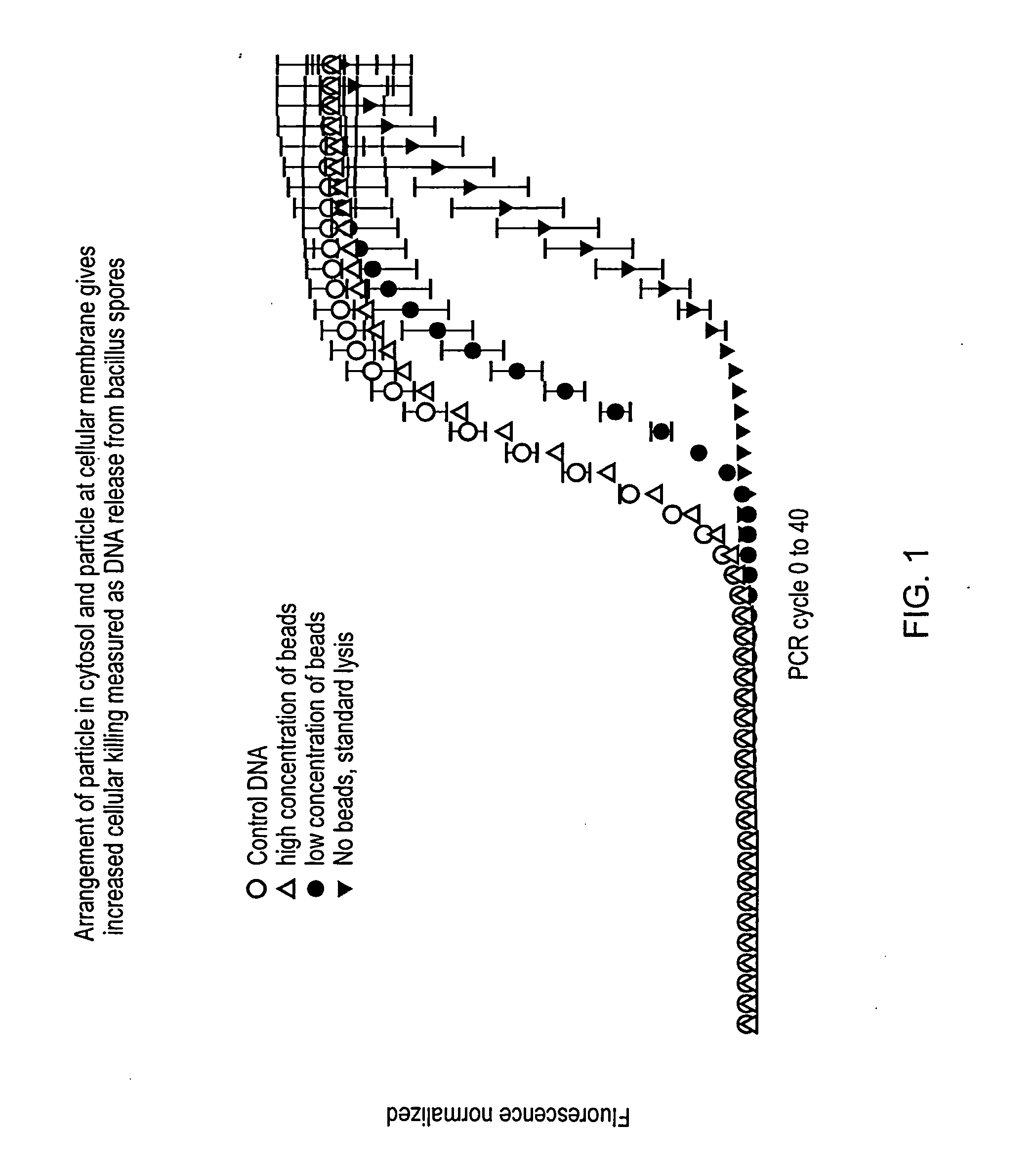
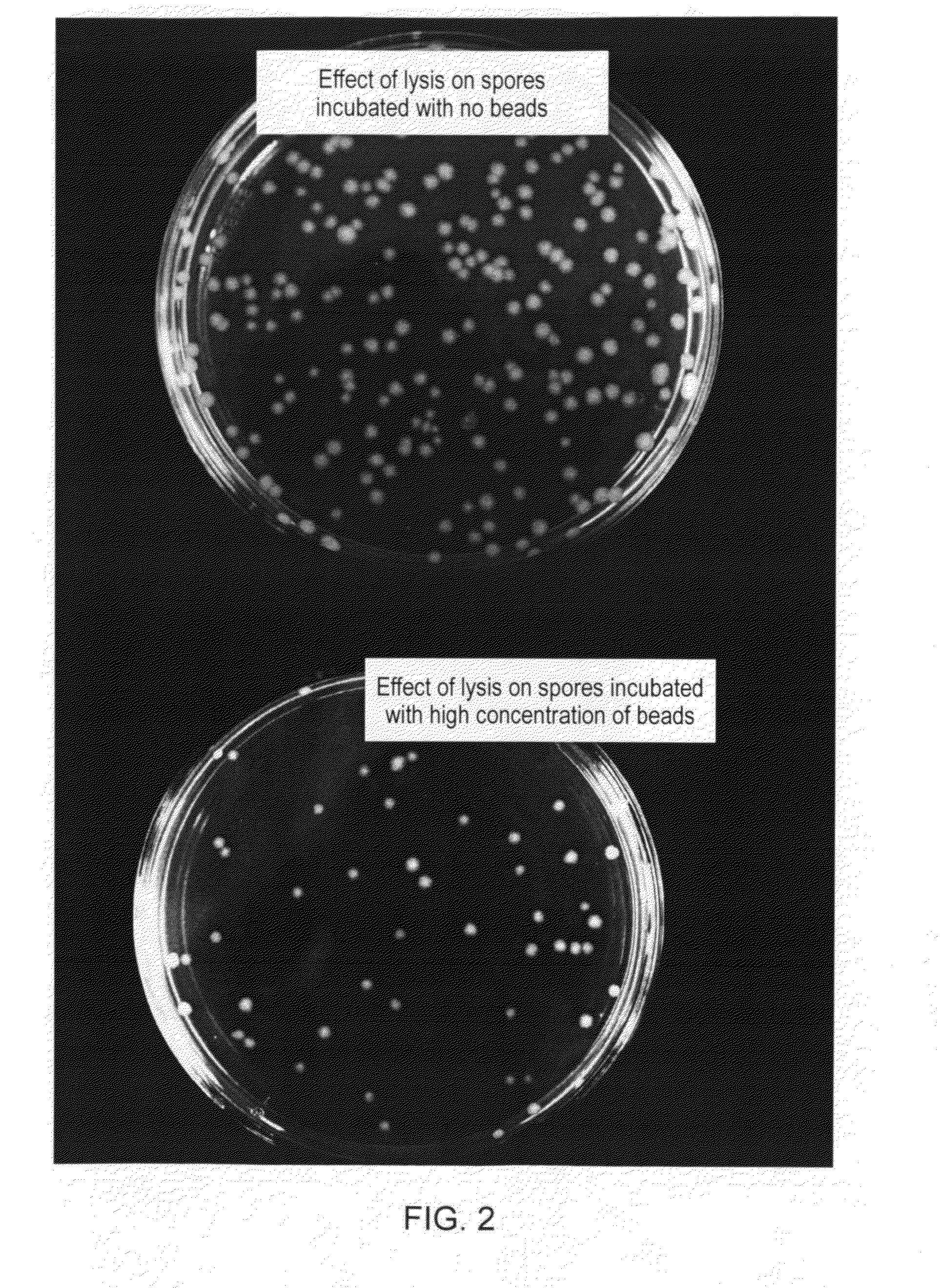
[0259]Voltage, time and frequency were kept constant (at 10 V, 30 sec and 100 KHz, respectively) variations was made in the concentration of iron oxide beads that was added respectively 2 and 0.5 μl 1 μM iron oxide silica coated beads (Merck). FIG. 1 shows the results of this experiment and as apparent, the high concentration of bead of 2 μl to the 12 μl spore sample showed a decrease in CT (threshol...


PUM

PropertyMeasurementUnit
Timeaaaaaaaaaa
Electric fieldaaaaaaaaaa

Abstract

A method, apparatus and system that employs particles, e.g., nanoparticles, and an electric or electro-magnetic field, to cause electroporation in target cells at reduced fields. Electroporation may be irreversible, leading to targeted cell death, or reversible, allowing species to be introduced into the target cell. The method introduces a particle to a position adjacent to the cell membrane of a target cell and exposes the target cell to a transient electromagnetic field for a time interval to cause targeted electroporation. A smaller electric field is applied, thereby surmounting similar methods. The particle enhances the effect of the electric field in its immediate vicinity, so reducing the field strength needed to achieve electroporation and thereby reducing the risk of damage to cells through high field exposure. Electroporation can be targeted to a subset of target cells by targeting the particles to surface markers on the target cell membrane.

Description

FIELD OF THE INVENTION[0001]The present invention relates to a method, apparatus and system for electroporation of cells. More particularly the invention relates to a method, apparatus and system that employs particles, or nanoparticles, together with an electric or electro-magnetic field to enhance electroporation in target cells. Electroporation may be reversible, or may be irreversible, so as to cause death of the target cells.[0002]1. Background of the Invention[0003]The use of electro-magnetic fields for treatment of cancer by causing lysis to cells that harbor, or are in close proximity to particles responsive to such fields, as a result of local heat deposition within or adjacent to the cells, is known. The techniques involve using a micro sized particle, typically below 0.1 μm, which for example comprises an iron oxide core and is coated with a polymer. Typically a secondary coating is applied where the particle is activated by chemicals that show specificity for biological ...

Claims


Application Information

Patent Timeline
IPC IPC(8): A61B18/00C12M1/42G01N27/00A61K39/395A61K38/02A61K31/7088A61K48/00C12N13/00A61K9/00B82Y5/00
CPCC12N13/00C12M35/02A61B2018/00613A61B18/18A61B19/5244C12N15/87A61B34/20
Inventor SOIKUM, SOIWISATHOMSEN, LARSDODGSON, JOHN ROBERT
Owner SOIKUM SOIWISA
Why Eureka
Try Eureka