

Spin Torque Transfer Magnetic Tunnel Junction Fabricated with a Composite Tunneling Barrier Layer
- Summary
- Abstract
- Description
- Claims
- Application Information
AI Technical Summary
Benefits of technology
Problems solved by technology
Method used
Image

Examples
second embodiment
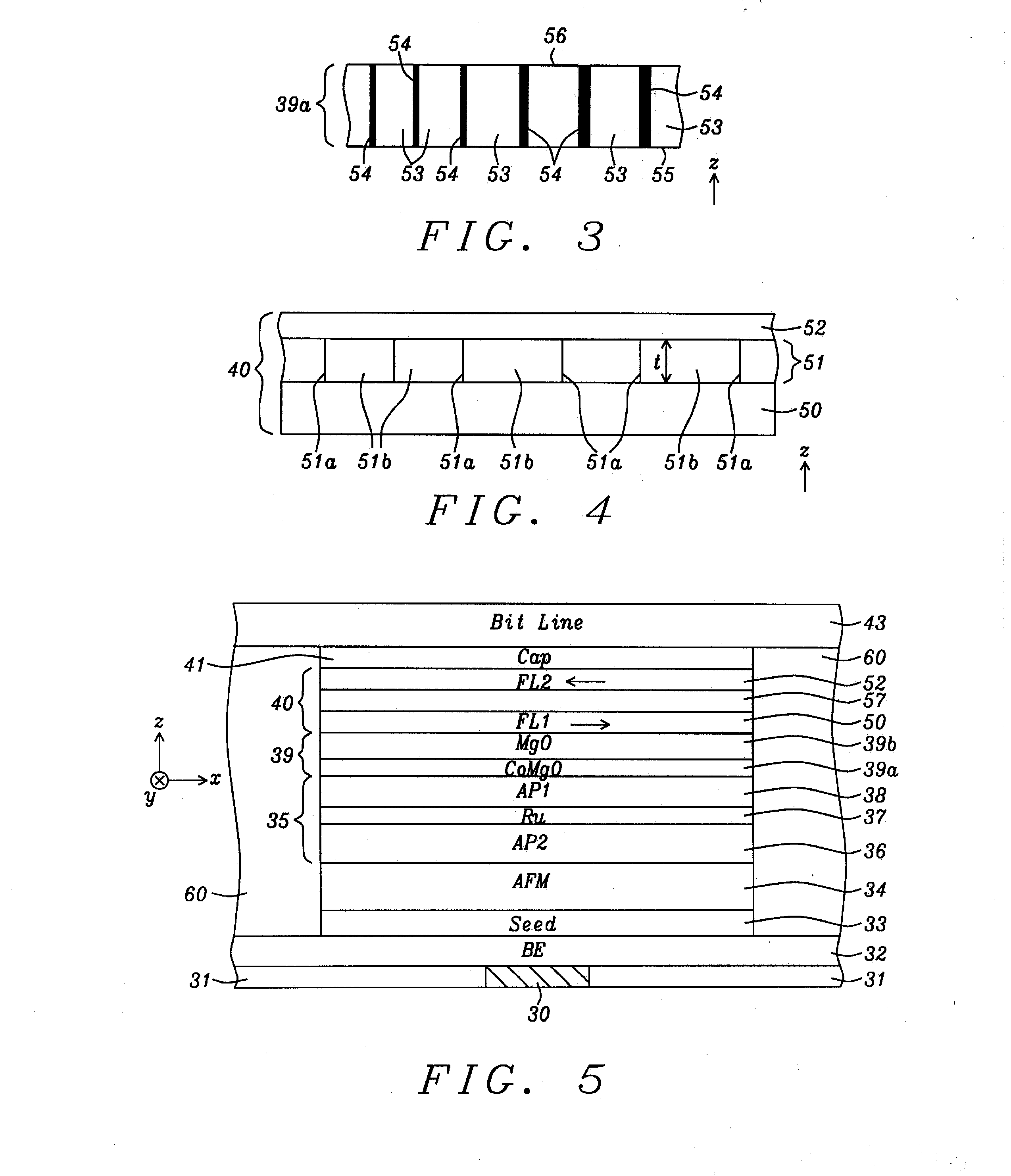
[0054]Referring to FIG. 4, free layer 40 may have a FL1 / NCC / FL2 configuration according to the present invention where a first ferromagnetic (FL1) layer 50 contacts the tunnel barrier layer 39, and a second ferromagnetic (FL2) layer 52 contacts an overlying cap layer 41. The NCC layer 51 has a thickness t and includes columns of a metal 51a such as Fe in an insulator matrix 51b such as SiO2. Preferably, the middle NCC layer 51 has a thickness t of 6 to 10 Angstroms that is essentially the same value in Angstroms as the minimum RM grain size in the RMO, RMN, or RMON NCC layer where R is Fe, Co, Ni, or an alloy thereof such as CoFe, M is a metal such as Si or Al, and RM grains are formed as conductive channels in the metal (M) oxide, metal nitride, or metal oxynitride insulator matrix. In one embodiment, M is Si, and RSiO, RSiN, and RSiON are composites in which conductive R(Si) grains such as Fe(Si) or Co(Si) are magnetically and electrically coupled with the adjacent magnetic layers...
third embodiment
[0059]Referring to FIG. 5, the present invention is illustrated and retains all of the features of the first two embodiments except the free layer 40 has a synthetic anti-ferromagnetic free (SyAF) configuration wherein the lower FL1 layer 50 is anti-ferromagnetically coupled to the upper FL2 layer 52 through a coupling layer 57 such as Ru. In one aspect, FL1 and FL2 layers may both be CoFeB and have in-plane magnetization. As a result, the net magnetization of the free layer 40 is reduced to approximately zero depending on the relative thicknesses of layers 50, 52 because of nearly equal and opposite magnetic moments in the FL1 and FL2 layers.
[0060]In related patent application Ser. No. 13 / 068,172, we described how including a moment dilution layer inserted in a free layer is beneficial in terms of improving thermal stability independently of the free layer moment, volume, crystal anisotropy while maintaining a high MR ratio in the spin valve element. In effect, the moment dilution ...
fourth embodiment
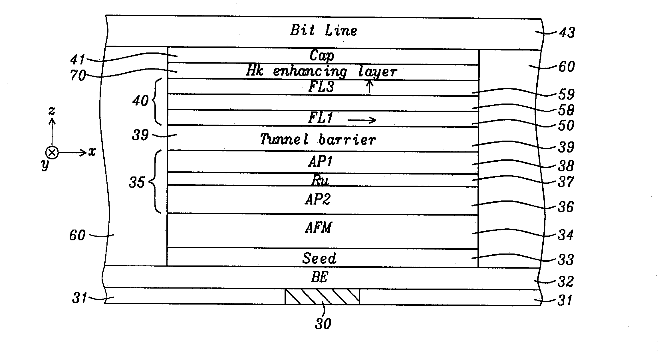
[0061]Referring to FIG. 6, the present invention is depicted in which a MTJ has PMA in at least the free layer 40. A moment diluting (Ms reducing) layer 58 such as Ta is inserted between the FL1 layer 50 having, in-plane anisotropy and a ferromagnetic FL3 layer 59 with perpendicular anisotropy in a composite free layer 40. The FL3 layer has a first interface with the moment diluting layer and a second interface with an overlying perpendicular Hk enhancing layer 70 to increase the perpendicular anisotropy field in the FL3 layer. In one embodiment, the free layer 40 has a CoFeB / Ta / CoFeB configuration wherein a top surface of the upper CoFeB layer contacts the perpendicular Hk enhancing layer 70. According to one aspect of the present invention, the FL1 layer interface with the tunnel barrier generates a sufficient perpendicular anisotropy field in the FL1 layer to partially cancel the demagnetization field of the FL1 layer while the magnetization in the FL1 remains in-plane. In an alt...
PUM
 Abstract
Description
Claims
Application Information