
Solar gasifier

a solar gasifier and gasifier technology, applied in the field of solar gasifiers, can solve the problems of increasing radiative losses, non-uniform temperature distribution of previous solar gasifiers, and reducing the efficiency of solar gasifiers, so as to improve heat capacity, enhance heat transfer, and improve efficiency

Active Publication Date: 2013-08-08
RGT UNIV OF MINNESOTA
View PDF3 Cites 8 Cited by
  • Summary
  • Abstract
  • Description
  • Claims
  • Application Information

AI Technical Summary

Benefits of technology

The present invention is a solar gasifier that has several technical advantages over other systems. It has improved heat transfer, which means it can produce more syngas with greater efficiency. It also reduces the formation of tar or ash, which are byproducts from gasification. The solar gasifier is designed to produce useful syngas without partially combusting the reactant, which reduces the amount of byproducts formed. Overall, the present invention is a more effective and efficient way to produce syngas from biomass.

Problems solved by technology

Biofuels such as corn ethanol and soybean biodiesel have been criticized for their low life cycle energy efficiency as well as for competing with food production for critical agricultural land.
However, obtaining the thermal energy at sufficiently high temperatures and rates to drive the process efficiently requires combustion of the feedstock or reliance on carbon intensive fossil energy sources.
For example, previous solar gasifiers experienced nonuniform temperature distributions in packed beds due to poor heat transfer.
Secondary products from gasification of biomass pose several issues.
The buildup of residual ash can increase radiative losses as well as insulate the reaction zone.
Packed beds are especially prone to tar production during startup.
Partial combustion can limit the energetic yield or require a dedicated oxygen facility to avoid dilution of the product gas.
This approach can at least partially avoid dilution of the product stream but does not reduce the losses in energetic yield of the feedstock.
As a result, changes in the operating conditions can result in a change of obtained kinetic parameters even though catalytic behavior cannot be present.
To obtain kinetically limited reaction rates, an excess of steam was delivered during the gasification runs, resulting in product gas compositions strongly skewed by the water gas shift reaction.

Method used


Image

  • Solar gasifier
  • Solar gasifier
  • Solar gasifier

Examples


Embodiment Construction

[0020]Reference will now be made in detail to certain embodiments of the disclosed subject matter, examples of which are illustrated in part in the accompanying drawings. While the disclosed subject matter will be described in conjunction with the enumerated claims, it will be understood that the exemplified subject matter is not intended to limit the claims to the disclosed subject matter.

Gasification

[0021]Gasification of biomass can encompass pyrolysis. Gasification can further encompass carbon or char gasification. The product of gasification can include synthesis gas (e.g., syngas), such as a blend of H2 and CO that can be combusted directly, or used as a precursor to generate liquid fuels, synthetic natural gas, or other hydrocarbons. Pyrolysis can include a rapid thermal dissociation reaction in which complex organic molecules, such as the biopolymers cellulose, hemicellulose or lignin, are decomposed at temperatures from about 550 to about 1300 K. With sufficiently fast heati...


PUM


Abstract

In various embodiments, the present invention provides a reaction chamber, including a catalyst, and a heating chamber configured to receive light. The heating chamber is positioned underneath at least a portion of the reaction chamber.

Description

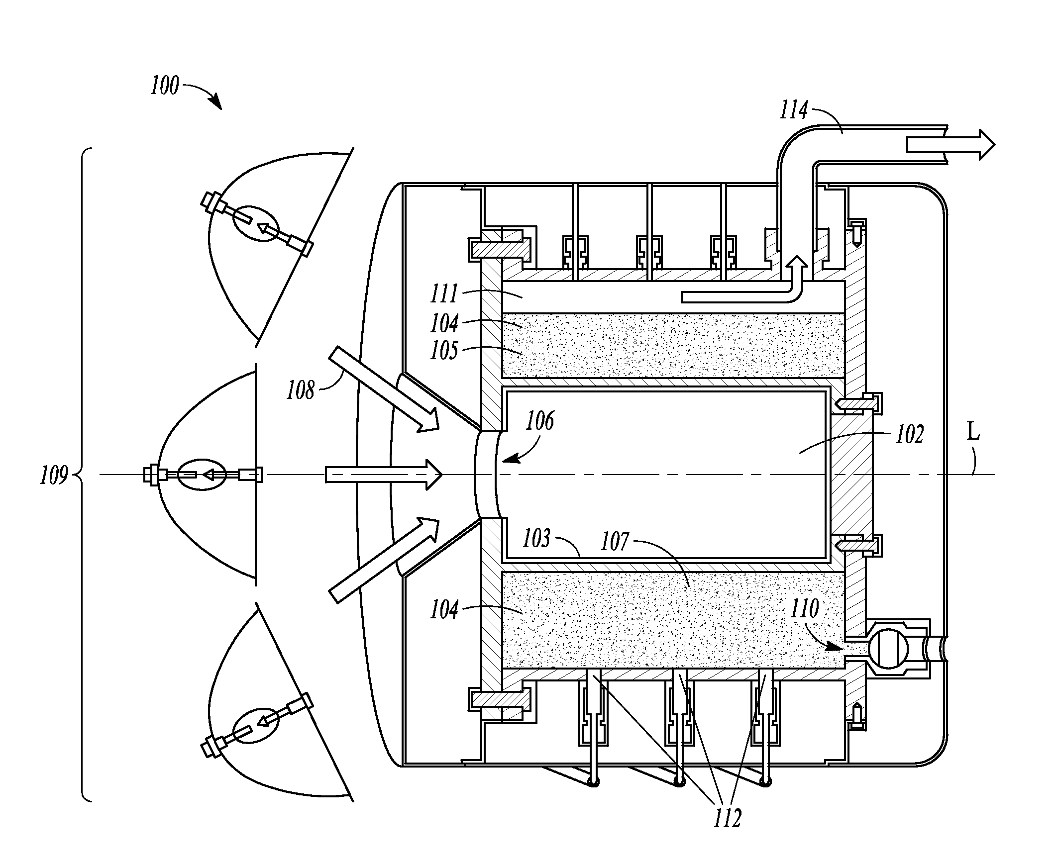
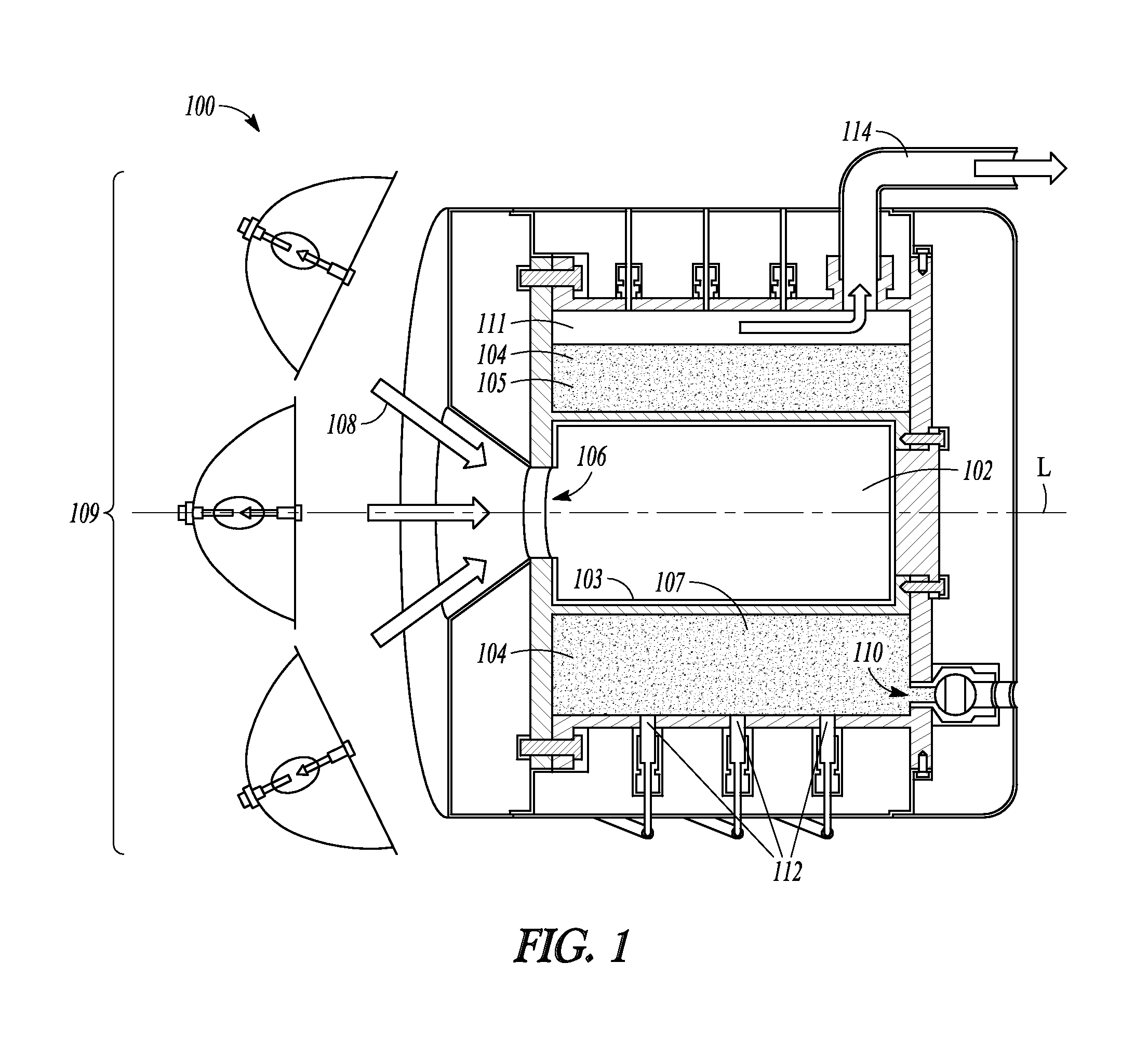
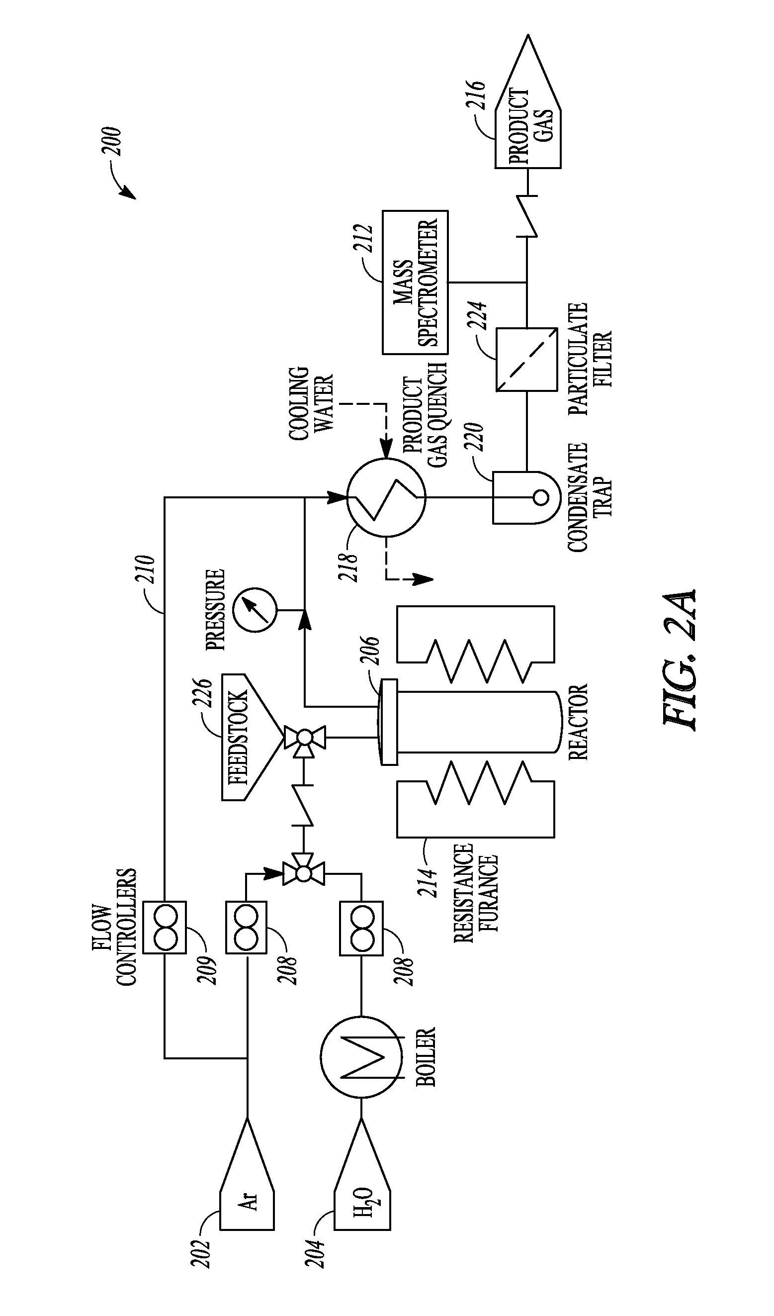
CLAIM OF PRIORITY[0001]This application claims the benefit of priority under 35 U.S.C §119(e) of Hathaway, U.S. Provisional Patent Application Ser. No. 61 / 595,779, entitled “SOLAR GASIFIER”, filed on Feb. 7, 2012, which is herein incorporated by reference in its entirety.BACKGROUND[0002]The world demand for energy is projected to increase by 40% over the course of the next 20 years and double by 2050. Liquid fuels derived from petroleum account for the largest share of global energy consumption, the majority consumed for transportation. One of the potential options for sustainable, low carbon fuels to replace fossil fuels is biofuel. Biofuels such as corn ethanol and soybean biodiesel have been criticized for their low life cycle energy efficiency as well as for competing with food production for critical agricultural land. Low-input biomass, such as mixed perennials, agricultural byproducts, or conservation reserve program (CRP) cuttings, offers the potential to produce life cycle ...

Claims


Application Information

Patent Timeline
IPC IPC(8): C10J3/72F24S20/20
CPCC10J3/72C10J3/57C10J2300/0916Y02E10/41C10J2300/0976C10J2300/1292F24J2/07C10J2300/092F24S20/20Y02E10/40
Inventor HATHAWAY, BRANDON J.DAVIDSON, JANE H.LIPINSKI, WOJCIECHKITTELSON, DAVID B.
Owner RGT UNIV OF MINNESOTA
Learn More