Negative electrode for secondary battery and secondary battery

a secondary battery and negative electrode technology, applied in the direction of active material electrodes, climate sustainability, sustainable manufacturing/processing, etc., can solve the problems of difficult to maintain the reliability of a battery, ensure reliability in terms of cycle characteristics, and increase the volume of the active material, so as to improve the charge and discharge cycle characteristics, reduce the effect of breakage and separation of active materials

Inactive Publication Date: 2013-09-12
SEMICON ENERGY LAB CO LTD
View PDF4 Cites 18 Cited by
  • Summary
  • Abstract
  • Description
  • Claims
  • Application Information

AI Technical Summary

Benefits of technology

[0028]As described above, in the case where the negative electrode is used in a secondary battery, high-speed charge and discharge are possible, and breakage and separation of the active material due to charge and discharge can be suppressed. In other words, a secondary battery with further improved charge and discharge cycle characteristics and high reliability can be manufactured.
[0029]According to one embodiment of the present invention, a negative electrode for a secondary battery which has high charge and discharge capacity, can be charged and discharged at high speed, and has little deterioration due to charge and discharge, and a secondary battery using the negative electrode can be provided. The negative electrode for a secondary battery includes at least a current collector including a plurality of protrusion portions and an active material layer covering the protrusion portions.
[0030]According to one embodiment of the present invention, with the use of a material containing titanium having higher strength than metals such as aluminum and copper for a current collector including a plurality of protrusion portions, a highly reliable negative electrode for a secondary battery and a secondary battery using the negative electrode can be provided.
[0031]Further, according to one embodiment of the present invention, a high molecular material layer covers part of negative electrode protrusion portions including basal portions thereof and a negative electrode base portion; thus, insertion of carrier ions into an active material layer provided over the basal portions of the protrusion portions of a current collector and a base portion of the current collector can be suppressed, and expansion and contraction of part of the active material layer over the basal portion or the base portion can be suppressed, resulting in prevention of separation and peeling of the active material layer.

Problems solved by technology

However, in Patent Document 1, when the negative electrode active material layer has either a columnar shape or a powder form and charge and discharge are repeated more than 10 cycles, which is described in the document, expansion and contraction of the volume cannot be avoided as long as the negative electrode active material occludes and releases carrier ions.
Thus, deformation and breakage of the negative electrode active material layer cannot be prevented, which makes it difficult to maintain the reliability of a battery.
This results from the fact that a portion where the current collector is in contact with the columnar structure body is limited to a bottom surface of the columnar structure body as well as expansion and contraction of the entire columnar structure.
Thus, the above structure has a problem in ensuring reliability in terms of cycle characteristics.
Consequently, the amount of reaction between silicon and carrier ions is reduced, which causes a reduction in charge and discharge capacity and makes it difficult to perform high-speed charge and discharge of a secondary battery.
Furthermore, since only the bottom portion of the columnar structure body of the active material described in Patent Document 1 is firmly attached to the rough surface of the current collector, the adhesion strength between the current collector and the active material is extremely low.

Method used


Image

  • Negative electrode for secondary battery and secondary battery
  • Negative electrode for secondary battery and secondary battery
  • Negative electrode for secondary battery and secondary battery

Examples


embodiment 1

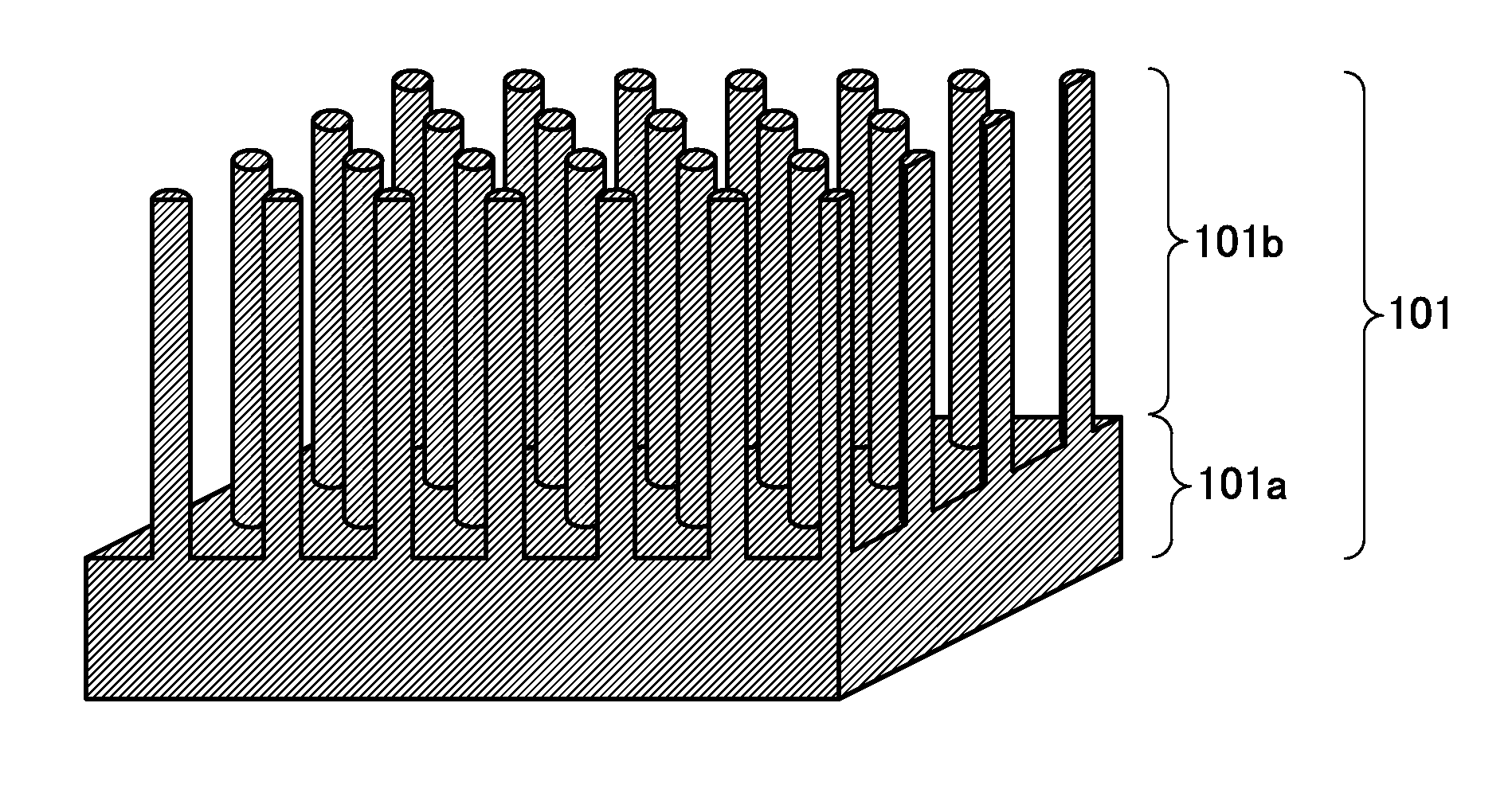
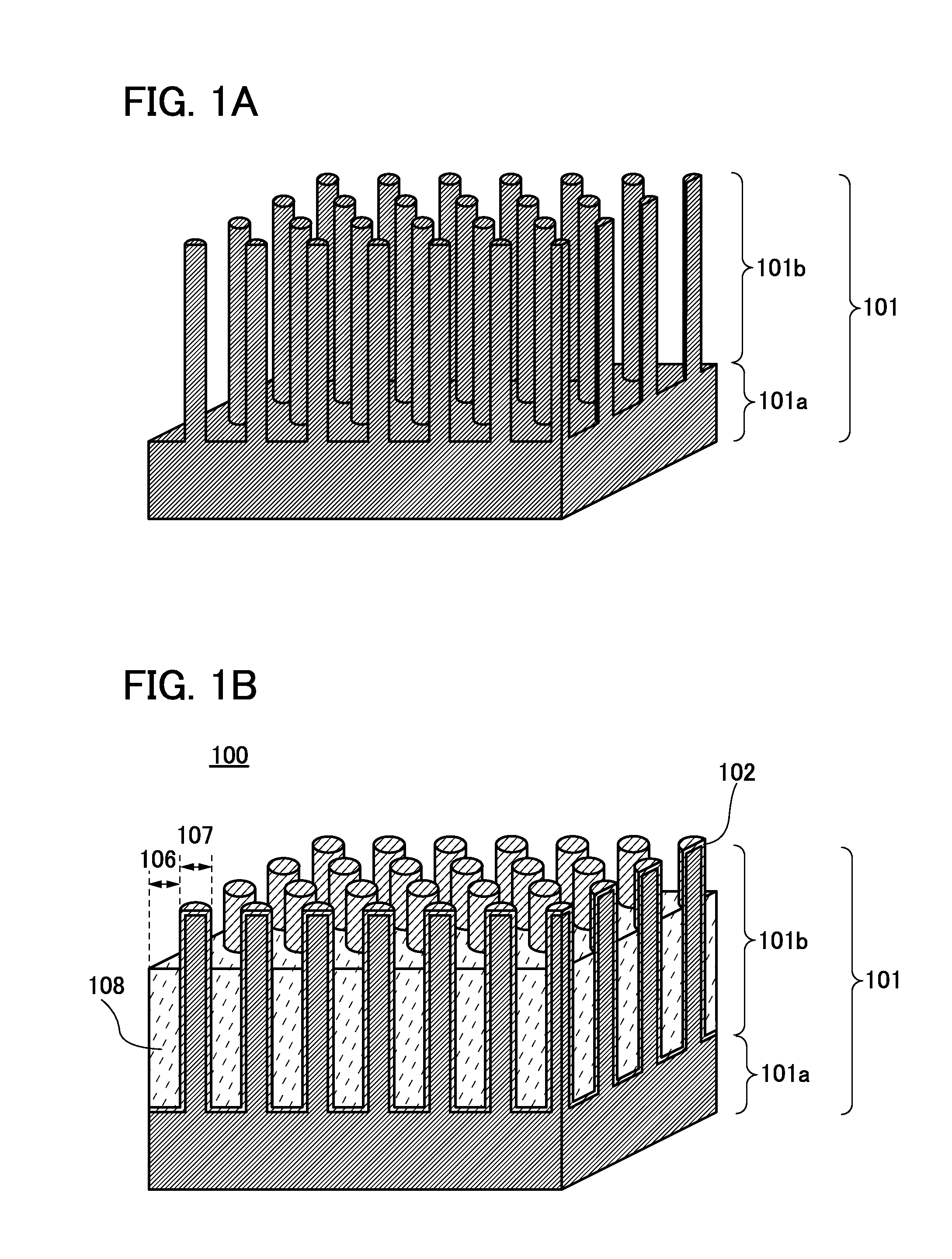
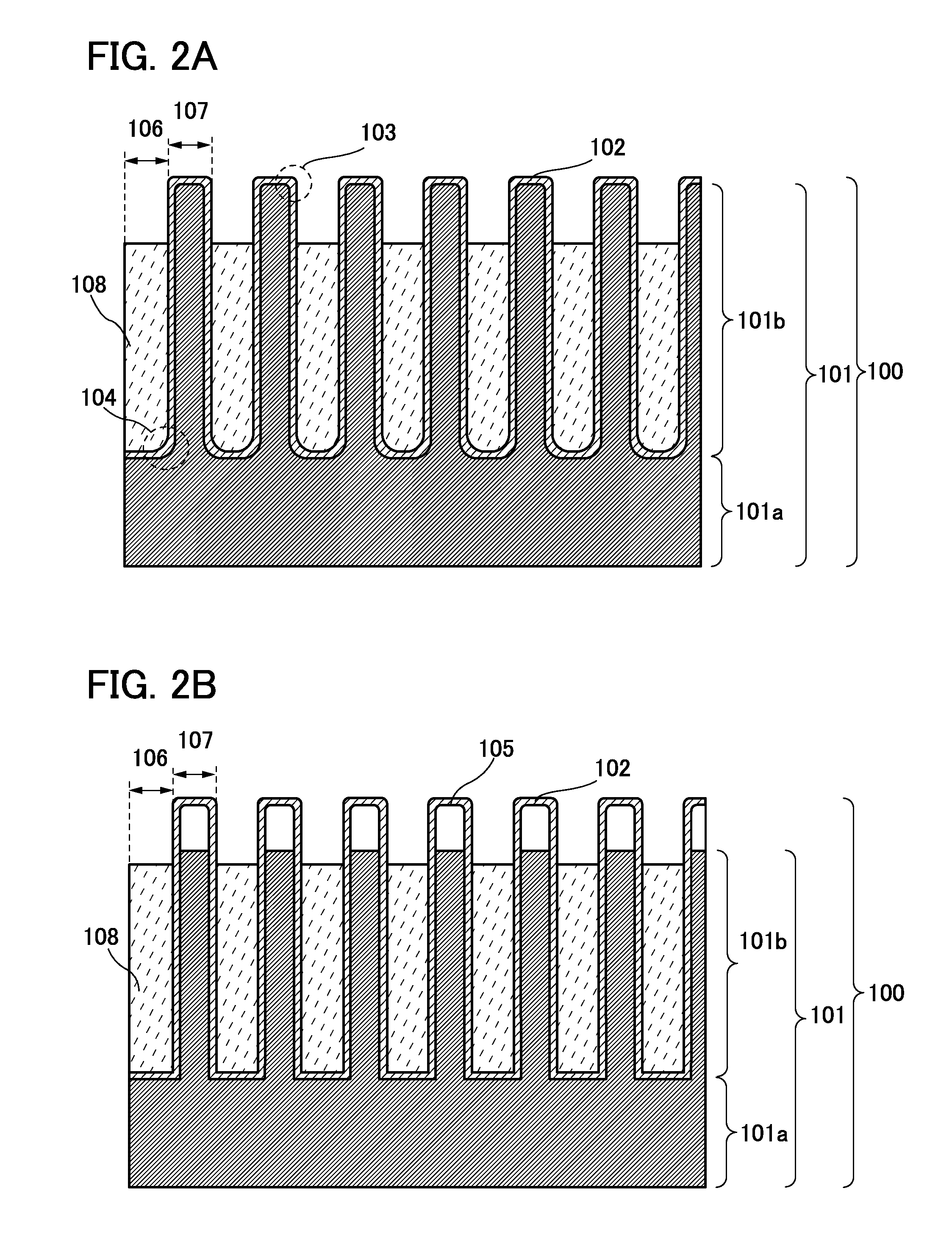
[0055]In this embodiment, a structure of a negative electrode for a secondary battery, which is less likely to deteriorate due to charge and discharge and has good charge and discharge cycle characteristics, and manufacturing methods of the negative electrode are described with reference to FIGS. 1A and 1B, FIGS. 2A and 2B, FIGS. 3A to 3I, FIGS. 4A to 4D, FIGS. 5A to 5D, FIGS. 6A to 6D, FIGS. 7A to 7D, and FIGS. 8A to 8C.

[0056]The secondary battery is a secondary battery in which a electrolyte solution is used and carrier ions are used for charge-discharge reaction. In particular, a secondary battery in which lithium ions are used as carrier ions is referred to as a lithium secondary battery. Examples of carrier ions which can be used instead of lithium ions include alkali-metal ions such as sodium ions and potassium ions; alkaline-earth metal ions such as calcium ions, strontium ions, and barium ions; beryllium ions; magnesium ions; and the like.

(Structure of Negative Electrode)

[00...

embodiment 2

[0144]In this embodiment, a structure and a manufacturing method of a secondary battery are described.

[0145]First, a positive electrode and a manufacturing method thereof are described.

[0146]FIG. 9A is a cross-sectional view of a positive electrode 300. In the positive electrode 300, a positive electrode active material layer 302 is formed over a positive electrode current collector 301.

[0147]The positive electrode current collector 301 can be formed using a material having high conductivity such as stainless steel, gold, platinum, zinc, iron, copper, aluminum, or titanium, or an alloy thereof. Alternatively, the positive electrode current collector 301 can be formed using an aluminum alloy to which an element which improves heat resistance, such as silicon, titanium, neodymium, scandium, or molybdenum, is added. Further alternatively, the positive electrode current collector 301 may be formed using a metal element which forms silicide by reacting with silicon. Examples of the metal...

embodiment 3

[0202]A secondary battery of one embodiment of the present invention can be used for power sources of a variety of electrical appliances which can operate by power.

[0203]Specific examples of electrical appliances using the secondary battery of one embodiment of the present invention are as follows: display devices of televisions, monitors, and the like, lighting devices, desktop personal computers and laptop personal computers, word processors, image reproduction devices which reproduce still images and moving images stored in recording media such as digital versatile discs (DVDs), portable CD players, portable radios, tape recorders, headphone stereos, stereos, table clocks, wall clocks, cordless phone handsets, transceivers, portable wireless devices, cellular phones, car phones, portable game consoles, toy, calculators, portable information terminals, electronic notebooks, e-book readers, electronic translators, audio input devices, video cameras, digital still cameras, electric ...


PUM

PropertyMeasurementUnit
aspect ratioaaaaaaaaaa
angleaaaaaaaaaa
angleaaaaaaaaaa

Abstract

A negative electrode for a secondary battery and a secondary battery using the negative electrode are provided. The negative electrode includes a current collector, an active material layer, and a high molecular material layer. The current collector includes a plurality of protrusion portions extending substantially perpendicularly and a base portion which includes the same material as the plurality of protrusion portions and is connected to the plurality of protrusion portions. The protrusion portions and the active material layer covering the protrusion portions form negative electrode protrusion portions. The base portion and the active material layer covering the base portion form a negative electrode base portion. Part of side surfaces of the negative electrode protrusion portions including basal portions thereof and a top surface of the negative electrode base portion are covered with the high molecular material layer.

Description

BACKGROUND OF THE INVENTION[0001]1. Field of the Invention[0002]The present invention relates to a negative electrode for a secondary battery and a secondary battery.[0003]2. Description of the Related Art[0004]In recent years, with the advance of environmental technology, power generation devices (e.g., solar power generation devices) having lighter environmental load than conventional power generation methods have been actively developed. Concurrently with the development of power generation technology, development of power storage devices, for example, secondary batteries such as lithium secondary batteries, lithium-ion capacitors, and air cells has also been underway.[0005]In particular, demand for secondary batteries have rapidly grown with the development of the semiconductor industry, as in the cases of electronic appliances, for example, portable information terminals such as cellular phones, smartphones, and laptop computers, portable music players, and digital cameras; med...

Claims


Application Information

Patent Timeline
Patent Type & Authority Applications(United States)
IPC IPC(8): H01M4/62
CPCH01M4/622Y02E60/122H01M4/134H01M4/70H01M4/386H01M4/661H01M4/1395Y02E60/10Y02P70/50
Inventor OGUNI, TEPPEITAJIMA, RYOTA
Owner SEMICON ENERGY LAB CO LTD
Why Eureka
Try Eureka