

Ceramic Composite for Light Conversion, Method for Producing Same, and Light Emitting Device Including Same
- Summary
- Abstract
- Description
- Claims
- Application Information
AI Technical Summary
Benefits of technology
Problems solved by technology
Method used
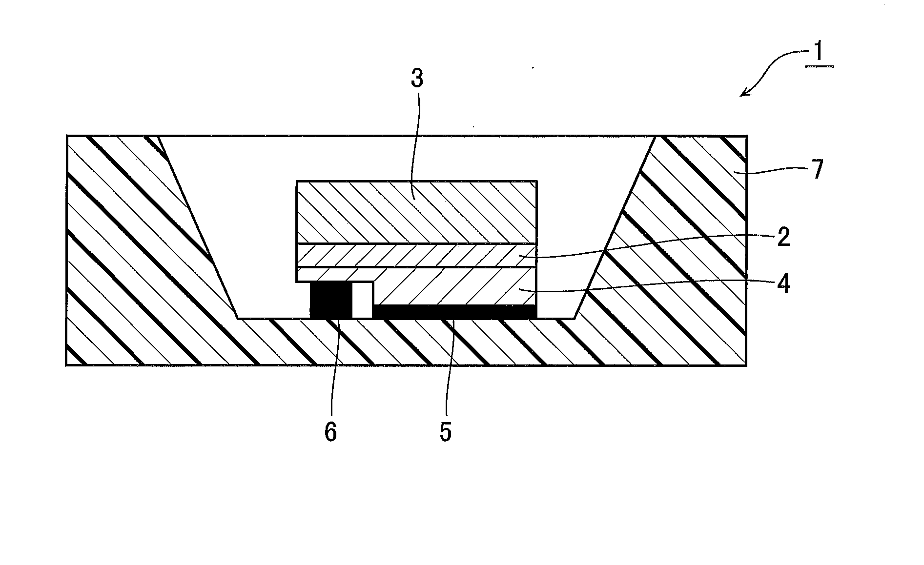
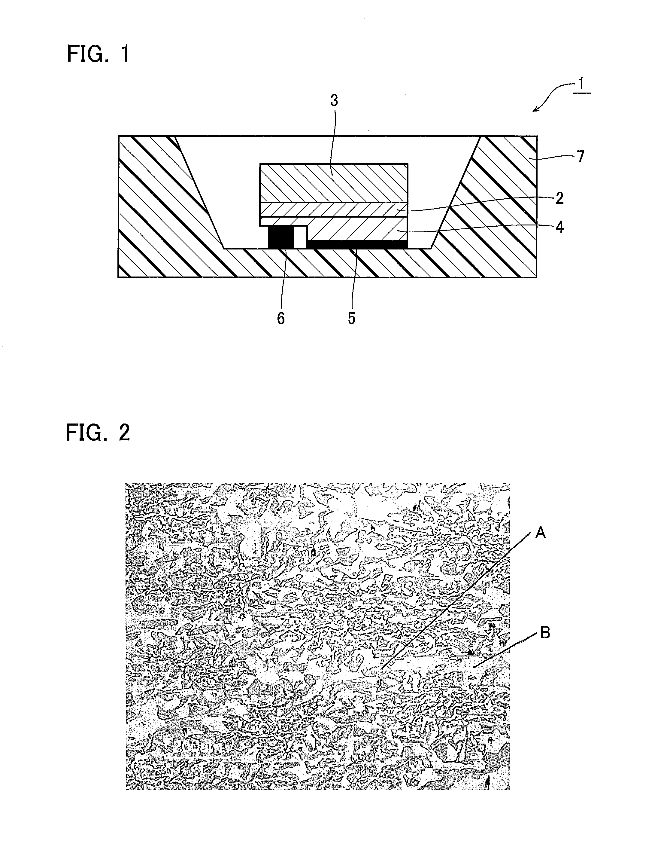
Image

Examples
example 1
[0062]An α-Al2O3 powder (purity: 99.99%), a Y2O3 powder (purity: 99.9%), and a CeO2 powder (purity: 99.9%) were weighed respectively so as to provide 0.81 mol in terms of AlO3 / 2, 0.19×0.997 mol in terms of YO3 / 2, and 0.19×0.003 mol. An SrCO3 powder (purity: 99.9%) was weighed so as to provide 0.3 parts by mass in terms of the oxide base on the 100 parts by mass of the mixture thereof. These powders were subjected to wet mixing in ethanol for 16 hours in a ball mill, and then the ethanol as a solvent was removed therefrom using an evaporator to obtain a starting material powder. The starting material powder was pre-molten in a vacuum furnace to obtain a starting material for unidirectional solidification.
[0063]Next, this starting material was directly put in a molybdenum crucible, the molybdenum crucible was set in a melting holding zone of an unidirectional solidification apparatus provided with the melting holding zone in an upper section and a cooling zone with a temperature gradi...
example 2
[0071]As the starting material, an α-Al2O3 powder (purity: 99.99%), a Y2O3 powder (purity: 99.9%), and a CeO2 powder (purity: 99.9%) were weighed respectively so as to provide 0.81 mol in terms of AlO3 / 2, 0.19×0.993 mol in terms of YO3 / 2, and 0.19×0.007 mol. A SrCO3 powder (purity: 99.9%) was weighed so as to provide 0.3 parts by mass in terms of the oxide base on the 100 parts by mass of the mixture thereof. Other than the above, a solidified body according to Example 2 was obtained in the same process as in Example 1, except that the moving speed of the molybdenum crucible was set at 10 mm / hour.
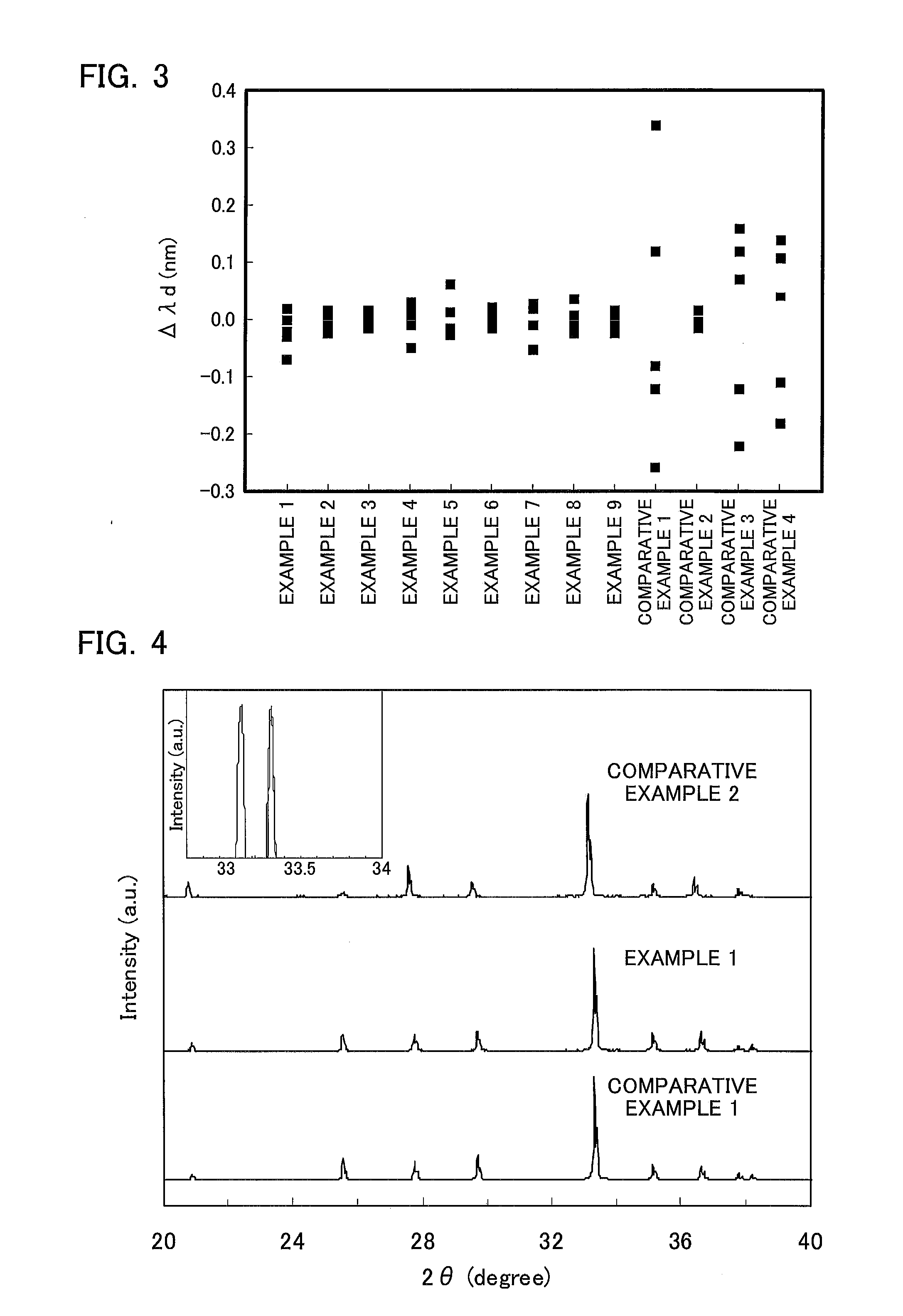
[0072]The fluorescence dominant wavelength (nm), the maximum variation obtained from the average value of the dominant wavelength and the fluorescence intensity were determined for the obtained solidified body in the same manner as in Example 1. The results are shown in Table 1. The variations of the dominant wavelength in the solidifying direction were 0.1 nm or less to the average value o...
example 3
[0073]As the starting material, an α-Al2O3 powder (purity: 99.99%), a Y2O3 powder (purity: 99.9%), and a CeO2 powder (purity: 99.9%) were weighed respectively so as to provide 0.81 mol in terms of AlO3 / 2, 0.19×0.996 mol in terms of YO3 / 2, and 0.19×0.004 mol. A SrCO3 powder (purity: 99.9%) was weighed so as to provide 0.4 parts by mass in terms of the oxide base on the 100 parts by mass of the mixture thereof. Other than the above, a solidified body according to Example 3 was obtained in the same process as in Example 1, except that the moving speed of the molybdenum crucible was set at 10 mm / hour.
[0074]The fluorescence dominant wavelength (nm), the maximum variation obtained from the average value of the dominant wavelength and the fluorescence intensity were determined for the obtained solidified body in the same manner as in Example 1. The results are shown in Table 1. The variations of the dominant wavelength in the solidifying direction were 0.1 nm or less to the average value o...
PUM
| Property | Measurement | Unit |
|---|---|---|
| Fraction | aaaaa | aaaaa |
| Percent by mass | aaaaa | aaaaa |
| Wavelength | aaaaa | aaaaa |
Abstract
Description
Claims
Application Information