Interpenetrating networks of carbon nanostructures and nano-scale electroactive materials

Inactive Publication Date: 2014-02-13
RGT UNIV OF CALIFORNIA
View PDF6 Cites 89 Cited by
  • Summary
  • Abstract
  • Description
  • Claims
  • Application Information

AI Technical Summary

Benefits of technology

[0018]In another embodiment, a composite electrode architecture is used that includes nano-sheets of an oxide material, such as titanium oxide, together with a nanostructured carbon such as graphene sheets or carbon nanot

Problems solved by technology

However, Li+ ion insertion is slow, limiting the power that can be delivered, and the charging time for these batteries is comparatively long.
Generally, supercapac

Method used


Image

  • Interpenetrating networks of carbon nanostructures and nano-scale electroactive materials
  • Interpenetrating networks of carbon nanostructures and nano-scale electroactive materials
  • Interpenetrating networks of carbon nanostructures and nano-scale electroactive materials

Examples


example 1

[0074]In order to demonstrate the functionality of various interpenetrating network films, three different fabrication methods for fabricating interpenetrating networks of graphene flakes and other nano-scale materials were used and the products were evaluated. The first method co-deposited graphene flakes and the nano-scale material using different dispersants for the two species. Each species was dispersed in separate solvents, sonicated to achieve appropriate dispersion, and sprayed using a nozzle that deposits both materials at the same time. Changing the concentration of the materials, and changing the deposition rate will lead to a different concentration of the material species in the composite films.

[0075]In one example, oxide nanoparticles were mixed with carbon graphene flakes and polyvinylidene fluoride (PVDF) binder in N-methyl-2-pyrrolidone to create a slurry. A stainless steel sheet was cut into an appropriate length and width and the slurry was painted onto the stainl...

example 2

[0079]To illustrate networks of oxide nanosheets, TiO2 nanosheets were prepared and evaluated. TiO2 nanosheets were produced by a simple hydrothermal route using tetrabutyl titanate, Ti(OBu)4, as a source and hydrofluoric acid solution as the solvent. The two were mixed in an autoclave at high temperature, above 180° C. After cooling to room temperature, centrifugation was used to separate the product, followed by washing ethanol and water. The TiO2 nanosheets that were produced were stable and could be stored in ethanol for electrode processing.

[0080]Graphene flakes were then mixed with a polyvinylidene fluoride (PVDF) binder (5 wt. %) in N-methyl-2-pyrrolidone solvent. The mixture was then sonicated for 1 hour. The TiO2 nanosheets dispersed in ethanol were then added to the mixture and sonicated. The resulting slurry was drop cast onto a stainless steel current collector of an appropriate length and width. The electrode / current collector was placed into an oven to evaporate the so...

example 3

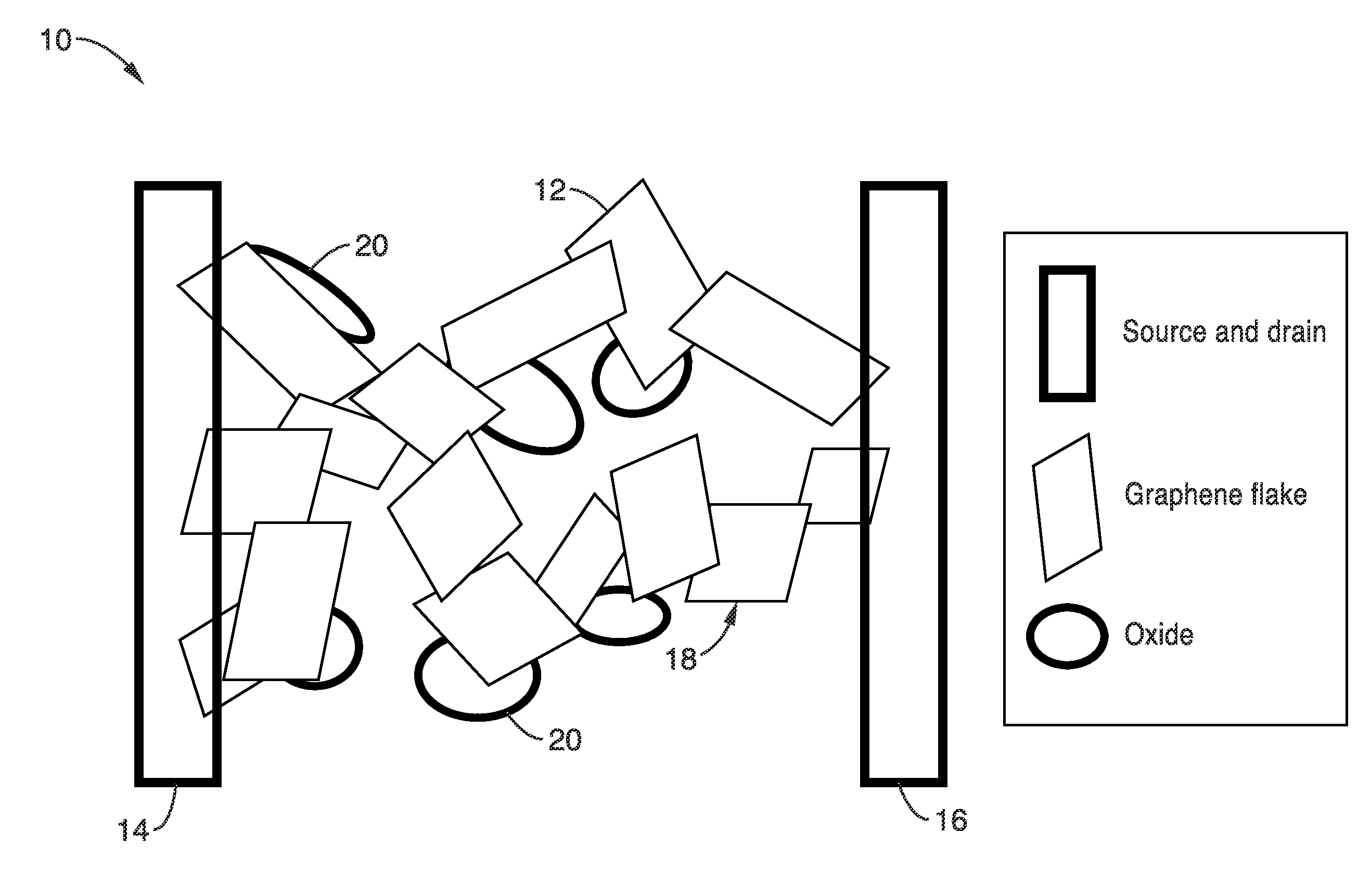
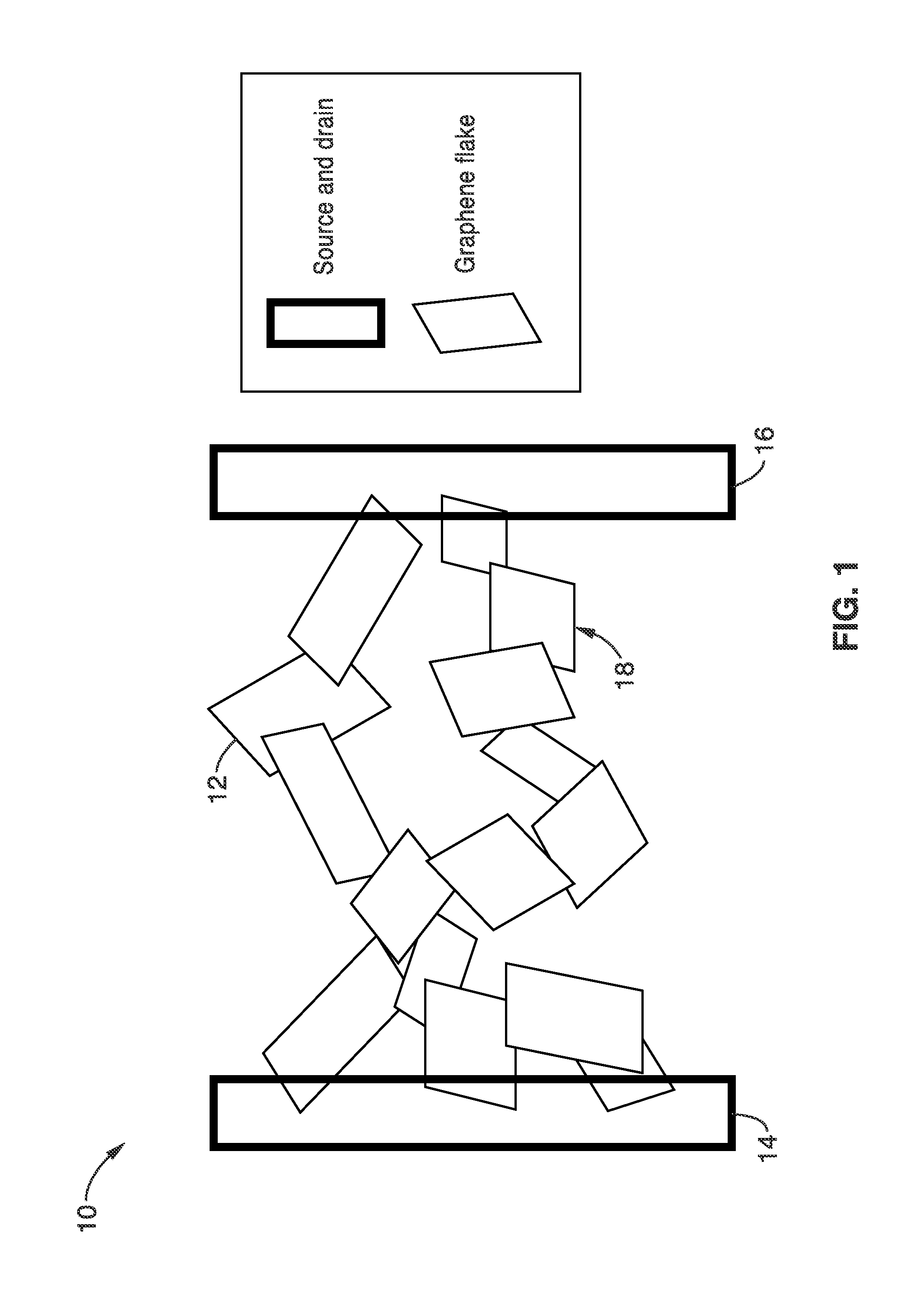
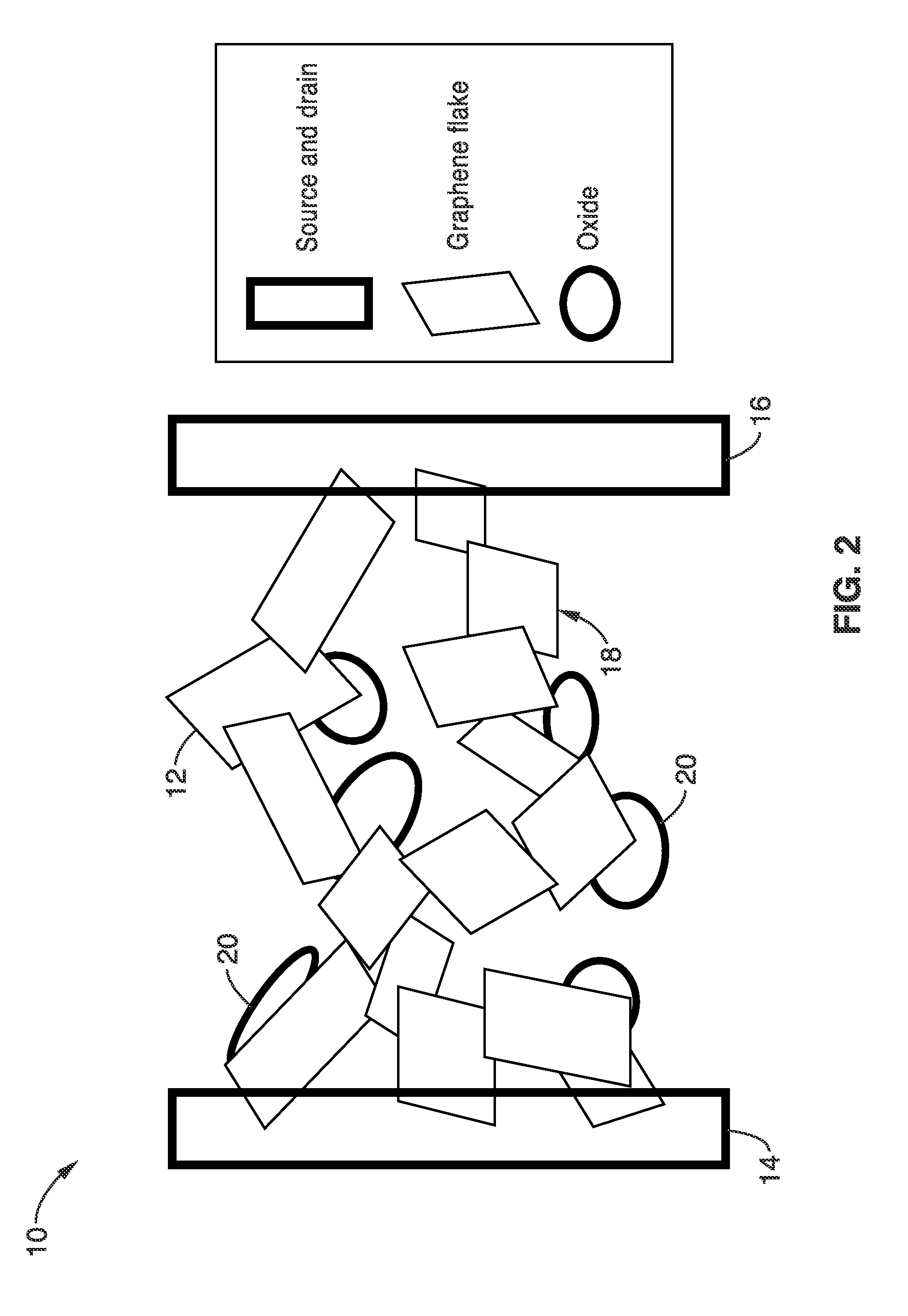
[0084]The functionality and performance of the electrodes with interpenetrating networks of graphene and materials with large electrochemical capacity for energy storage devices were evaluated. As described above, the electrodes take advantage of both the high conductivity of the graphene and the high specific capacitance of the oxides. The direct electrical contact between the two species ensures that the charges generated by the electrochemical reaction at the surface of the oxide materials will be transferred to the graphene network. Thus high energy density and high power density are ensured.

[0085]In one exemplary embodiment of the present invention, an asymmetric supercapacitor may be assembled with an anode comprising interpenetrating networks of carbon graphene and oxide nanoparticles and a cathode comprising interpenetrating networks of graphene and a carbonaceous material (e.g., activated carbon). It should be noted that one or both of the interpenetrating networks of graph...


PUM


Abstract

An interpenetrating network assembly with a network of connected flakes of nano-scale crystalline carbon and nano-scale particles of an electroactive material interconnected with the carbon flakes is provided. The network assemblies are particularly suited for energy storage applications that use metal oxide electroactive materials and a single charge collector or a source and drain. Interpenetrating networks of graphene flakes and metal oxide nanosheets can form independent pathways between source and drain. Nano-scale conductive materials such as metal nanowires, carbon nanotubes, activated carbon or carbon black can be included as part of the conductive network to improve charge transfer.

Description

CROSS-REFERENCE TO RELATED APPLICATIONS[0001]This application is a 35 U.S.C. §111(a) continuation of PCT international application number PCT / US2012 / 025523 filed on Feb. 16, 2012, incorporated herein by reference in its entirety, which is a nonprovisional of U.S. provisional patent application Ser. No. 61 / 443,434 filed on Feb. 16, 2011, incorporated herein by reference in its entirety. This application is a nonprovisional of U.S. provisional patent application Ser. No. 61 / 682,140 filed on Aug. 10, 2012, incorporated herein by reference in its entirety.[0002]The above-referenced PCT international application was published as PCT International Publication No. WO 2012 / 112818 on Aug. 23, 2012 and republished on Oct. 18, 2012, and is incorporated herein by reference in its entirety.STATEMENT REGARDING FEDERALLY SPONSORED RESEARCH OR DEVELOPMENT[0003]Not ApplicableINCORPORATION-BY-REFERENCE OF MATERIAL SUBMITTED ON A COMPACT DISC[0004]Not ApplicableBACKGROUND OF THE INVENTION[0005]1. Fiel...

Claims


Application Information

Patent Timeline
IPC IPC(8): H01M4/36H01M4/583H01L29/16H01G9/042H01G9/048H01L29/15H01M4/48H01M4/64
CPCH01M4/364H01M4/48H01M4/583H01L29/1606H01G9/042H01G9/048H01L29/15H01M4/64H01L29/775H01L29/127H01L29/0673H01G11/24H01G11/30B82Y10/00H01M4/131H01M4/481H01M4/485H01M4/502H01M4/505H01M4/523H01M4/5825H01M4/624H01M4/625Y10T428/25Y02E60/10Y02E60/13
Inventor GRUNER, GEORGEDUAN, XIANGFENGDUNN, BRUCE S.AUGUSTYN, VERONICA
Owner RGT UNIV OF CALIFORNIA
Why Eureka
Try Eureka