Porous oxide electrode layer and method for manufacturing the same

a technology of porous oxide and electrode layer, which is applied in the direction of electrochemical generators, cell components, coatings, etc., can solve the problems of easy cracks, high cost, and more time-consuming methods, and achieves low cost, low cost, and uniform thickness.

Inactive Publication Date: 2014-04-24
NAT TAIWAN UNIV
View PDF3 Cites 7 Cited by
  • Summary
  • Abstract
  • Description
  • Claims
  • Application Information

AI Technical Summary

Benefits of technology

[0008]In order to produce porous oxide electrode layer with few cracks, high conductivity and uniform thickness at low cost, this invention provides a method for manufacturing porous oxide electrode layer; the method combines colloidal dispersion, spin coating and calcinations steps; the method comprises: preparing an electrode slurry containing an electrically conductive oxide material powder, a dispersant, water and a moisture agent; spin coating the electrode slurry on a surface of a fine electrolyte layer or a porous substrate, and simultaneously controlling the thickness and uniformity of the electrode slurry on the fine electrolyte or the porous substrate; and calcining the electrode slurry on the fine electrolyte layer or the porous substrate to form a porous electrode.
[0009]To enhance the maximal power density of the solid oxide fuel cell and increase the density of triple phase boundaries, said electrode slurry can further contain yttria-stabilized zirconia (YSZ); after the steps of spin coating and calcination, the electrically conductive oxide and YSZ form composite electrode on the fine electrolyte layer or on the porous substrate.
[0010]To ameliorate the problem of the cracks incurred during manufacturing, this invention proposes to add polyethylene glycol (PEG) with a low molecular weight into the electrode slurry as a moisture agent to reduce the cracks on the fabricated electrode and lower the area specific resistance of the interface between the electrode and the electrolyte, wherein the molecular weight of the PEG ranges from 200 to 1500.
[0011]During the spin coating step, if the electrode slurry is not thick or viscous enough, the fabricated electrode will not have enough thickness even after several times of spin coating; therefore, this invention proposes to add aqueous binder to increase the viscosity of the electrode slurry, then the thickness of the fabricated electrode can be controlled during the process of this invention.
[0012]Different electrode material powders have different average particle diameters; for an electrode made from an electrode material powder with a small average particle diameter, the amount of the cracks in the fabricated electrode can be satisfactorily small even without the moisture agent added; therefore, this invention provides another similar method for manufacturing porous oxide electrode layer, comprising: preparing an electrode slurry containing an electrically conductive oxide material powder, a dispersant, water and a binder; spin coating the electrode slurry on a surface of a fine electrolyte or a porous substrate and simultaneously controlling the thickness and uniformity of the electrode slurry on the fine electrolyte or the porous substrate; and calcining the electrode slurry on the fine electrolyte or the porous substrate to form a porous electrode.
[0013]With the method for manufacturing porous oxide electrode layer provided by this invention, different electrode materials can be selected to prepare the electrode slurry for spin coating; by adjusting the solid loading of the slurry, selecting the proper binder and moisture agent, and adjusting the concentration of the binder and moisture agent in the slurry, the thickness and quality of the fabricated electrode can be controlled, and porous oxide electrodes with a uniform thickness, few cracks and low contact resistance to the electrolyte can be fabricated at low cost.

Problems solved by technology

On the other hand, for higher power efficiency and better stacking structure, other manufacturing methods such as chemical vapor deposition (CVD), plasma chemical vapor deposition (PCVD), combustion chemical vapor deposition (CCVD), or combustion spray are developed; certainly, these methods are more time-consuming, and the costs are higher; therefore, they are usually applied in research works and rarely applied in mass production.
The structure of a SOFC electrode is a porous film, and cracks are brought forth easily during the manufacturing process.
The cracks reduce the current collection capability, increase the resistance and decrease the output power.

Method used


Image

  • Porous oxide electrode layer and method for manufacturing the same
  • Porous oxide electrode layer and method for manufacturing the same
  • Porous oxide electrode layer and method for manufacturing the same

Examples


embodiment 1

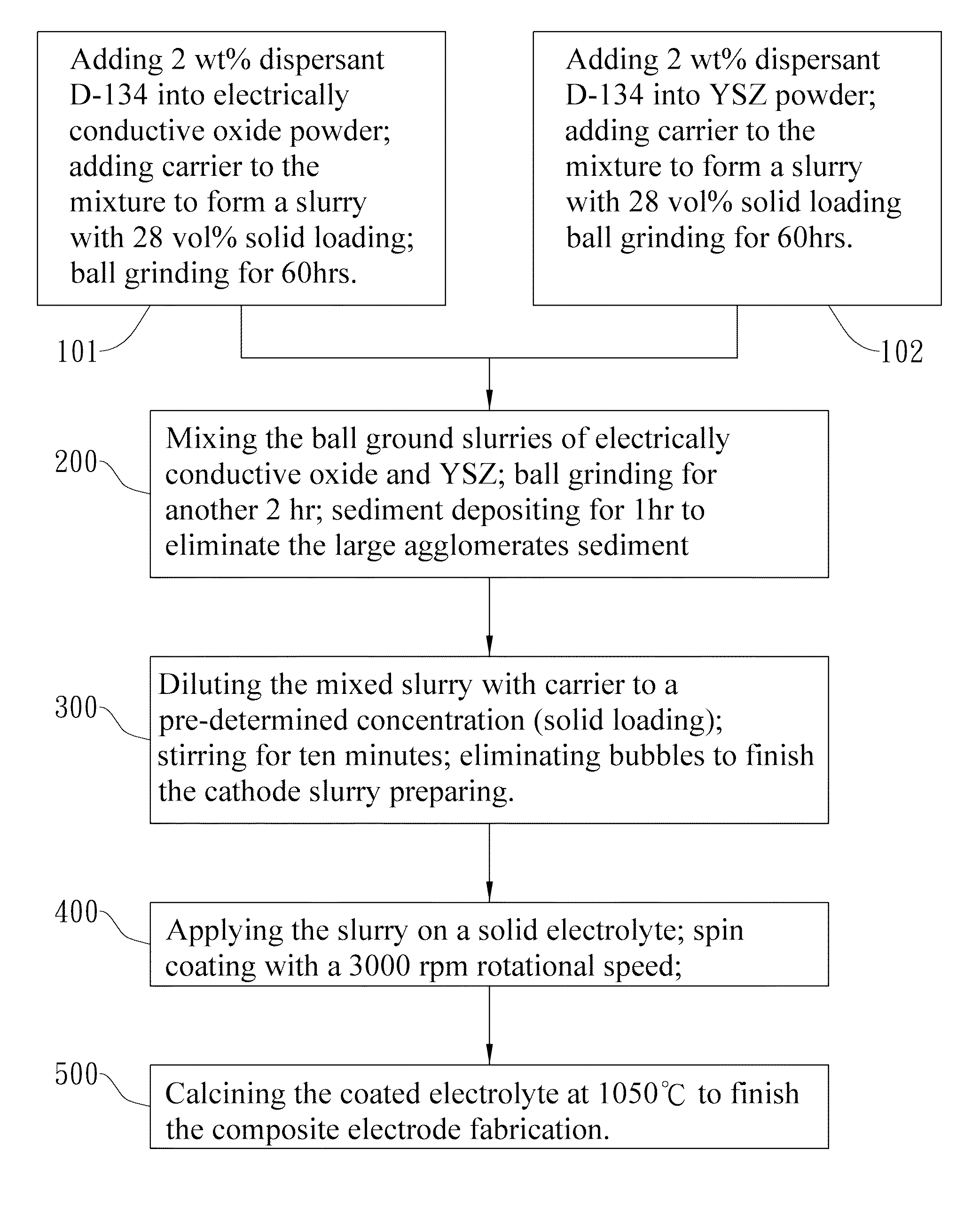
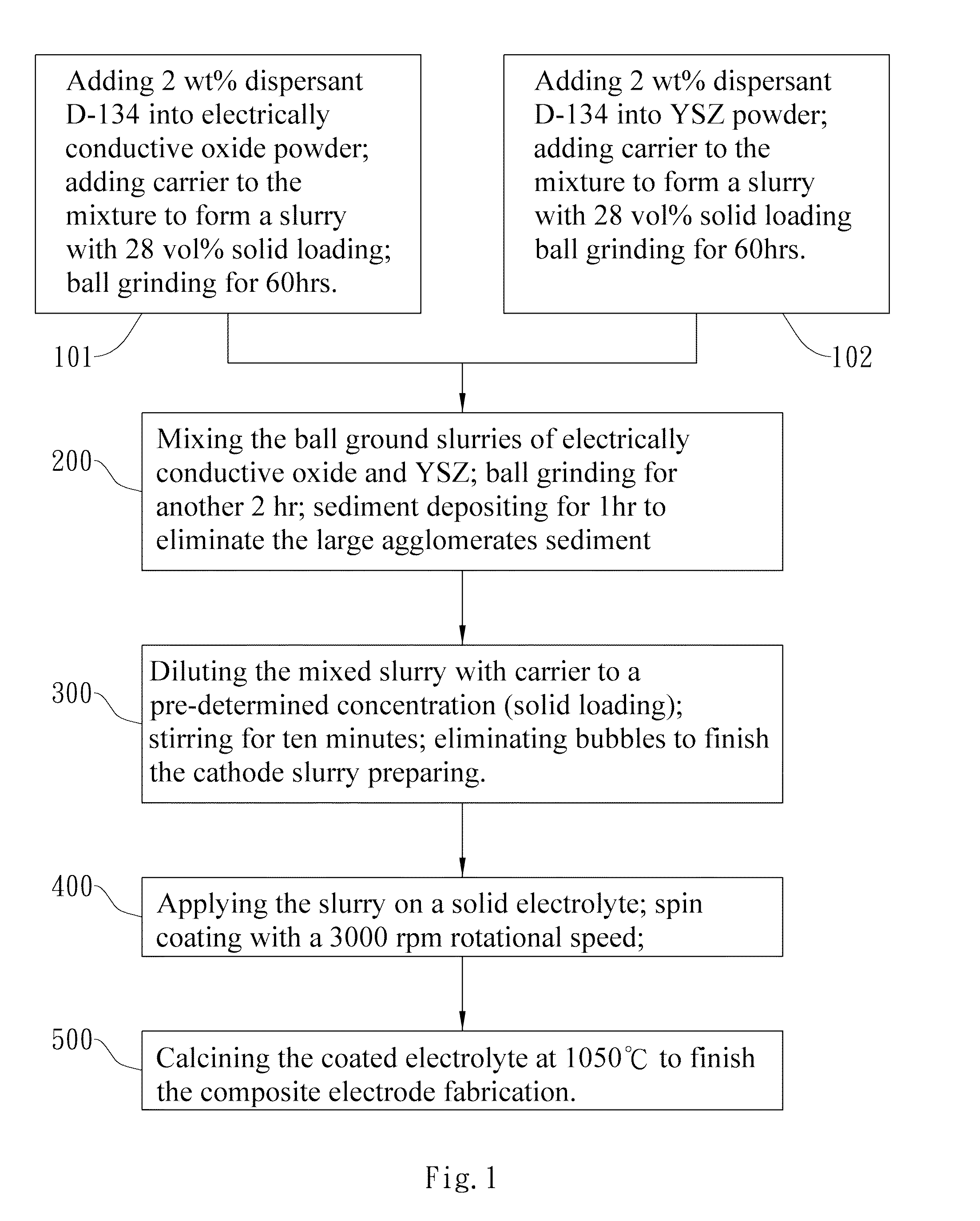
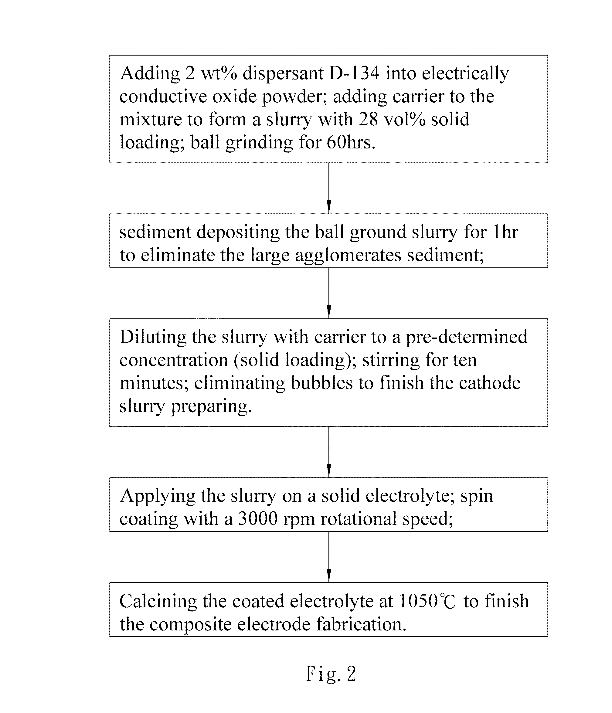
[0029]In table 1, simple electrode material means LSM or LSCF, and composite electrode material means LSM with YSZ added or LSCF with YSZ added; in the composite electrode slurry samples (i.e. samples 1˜11), the weight ratios of LSM:YSZ and the weight ratios of LSCF:YSZ are all 1:1. The LSCF material used in these embodiments is La0.6Sr0.4Co0.2Fe0.8O3 (abbreviated as LSCF). The solid loading in table 1 means the weight percentage of the solids in the prepared slurry, which is ready for the spin coating step. The carrier in table 1 is water, polyethylene glycol with an average molecular weight around 200 (PEG200), or the mixture of the two, wherein the weight ratios of water:PEG200 in the carriers are given in table 1. The PVA concentrations given in table 1 are the weight % based on the powder mass in the prepared slurry, wherein PVA is added as binder. The method for preparing the slurry samples in this invention is demonstrated by the preparing of the water-based (water as the car...

first embodiment

[0032]this invention is to explore the relationship between the solid loading of the slurry and the thickness of the fabricated electrode. The water-based composite electrode slurry with a 15 wt % solid loading (table 1, sample 1, deionized water as the carrier) is spin-coated on a thin solid electrolyte layer for 5 seconds with a rotational speed of 3000 rpm. The coated electrolyte is calcined at 1050° C. for one hour to form the composite electrode film on the solid electrolyte. The thickness of this made composite electrode is only about 800 nm; the reasons for this thickness are as follows: the viscosity of the water-based composite electrode is too low, and the slurry is spin-coated on a fine solid electrolyte layer; therefore, most of the deposited slurry is thrown away from the surface of the electrolyte.

[0033]The composite electrode slurry with a 30 wt % solid loading (table 1, sample 2) is used for manufacturing the electrode with the same process, and the thickness of the ...

second embodiment

[0034]this invention explores the effect of adding binder to the electrode slurry to increase the viscosity of the slurry; in this embodiment, PVA is used as the binder. Slurry sample 4 in table 1 is water-based LSM+YSZ composite electrode slurry; the solid loading of this slurry is 50 wt %, and the PVA concentration is 5 wt %. The experimental result shows the additional PVA helps to increase the thickness of the fabricated composite electrode; however, the uniformity deteriorates as shown by FIG. 4, wherein FIG. 4(a) and FIG. 4(b) are scanning electron microscope (SEM) images of the surface of the electrode made from slurry sample 4 with different magnifications, and FIG. 4(c) is the cross-sectional SEM image of the electrode. The agglomerations shown in FIG. 4(a) and FIG. 4(b) may be the result of the incompletely dissolved PVA. This embodiment also explores the effect of the additional PVA to the LSCF+YSZ composite electrode; the slurry samples used are samples 5, 6 and 7 in tab...


PUM

PropertyMeasurementUnit
porosityaaaaaaaaaa
thicknessaaaaaaaaaa
porosityaaaaaaaaaa

Abstract

This invention provides a method for manufacturing porous oxide electrode layer, comprising: preparing an electrode slurry containing an electrically conductive oxide material powder, a dispersant, water and a moisture agent; spin coating the electrode slurry on a surface of a thin electrolyte or a porous substrate and simultaneously controlling the thickness and uniformity of the electrode layer on the fine electrolyte or the porous substrate; and calcining the electrode layer on the fine electrolyte or the porous substrate to form a porous electrode.

Description

BACKGROUND OF THE INVENTION[0001]1. Field of the Invention[0002]The present invention relates to porous oxide electrode layer, and more particularly, to a porous oxide electrode layer used in solid oxide fuel cells.[0003]2. Description of the Related Art[0004]A solid oxide fuel cell (SOFC) is an electricity-generating apparatus featuring high power conversion efficiency and low pollution; therefore, it becomes more important in recent years. The principles of operation are as follows: supply oxygen gas or air into the cathode of a SOFC; supply natural gas, hydrogen or other gaseous feuls into the anode of the SOFC; by the reduction occurring at the cathode and the oxidation occurring at the anode of the cell, electricity and gaseous waste produced from the electrochemical reactions of the fuel gases are generated. The cathode and anode structures of a SOFC are similar; both of them are porous, electrically conductive films; however, these two electrodes are the places where reductio...

Claims


Application Information

Patent Timeline
Patent Type & Authority Applications(United States)
IPC IPC(8): H01M4/88
CPCH01M4/88H01M4/8621H01M4/8668H01M4/881H01M4/8828H01M4/8885H01M4/9033H01M2008/1293Y02E60/50
Inventor WEI, WEN-CHENG J.LIN, TING-YULIN, SUNG-EN
Owner NAT TAIWAN UNIV
Why Eureka
Try Eureka