Highly Conductive Nano-structures incorporated in Semiconductor Nanocomposites

a nano-composites, high-conductive technology, applied in the field of carbon-based nano-composites, can solve the problems of limited electron transport in nanoparticle-based devices, low efficiency, and low efficiency, and achieve the effect of reducing electron loss and improving charge transfer in semiconductor photoanodes

Active Publication Date: 2014-06-12
THE HONG KONG POLYTECHNIC UNIV
View PDF2 Cites 26 Cited by
  • Summary
  • Abstract
  • Description
  • Claims
  • Application Information

AI Technical Summary

Benefits of technology

[0024]Unlike the traditional nanocomposite used for DSSC, the nanocomposite of the presently claimed invention provides several advantages. The configuration of the nanocomposite of the presently claimed invention is able to improve charge transfer in the semiconductor photoanode once an electron is injected there from the sensitzied dye, and reduce the loss of electrons from recombination with the o

Problems solved by technology

However, electron transport in nanoparticle-based device is limited by a trap-limited diffusion process.
The slow charge diffusion increases the probability of recombination, resulting in lower efficiency.
Moreover, the grain boundaries encountered during electron transport lead to fast recombination prior to their collection at the electrode.
However, regarding the two fore-mentioned architectures in the prior arts, the electron transfer routes for the generated electrons to travel from the generation sites to the CNTs are long and many electrons are susceptible to recombine with the h

Method used


Image

  • Highly Conductive Nano-structures incorporated in Semiconductor Nanocomposites
  • Highly Conductive Nano-structures incorporated in Semiconductor Nanocomposites
  • Highly Conductive Nano-structures incorporated in Semiconductor Nanocomposites

Examples


example 1

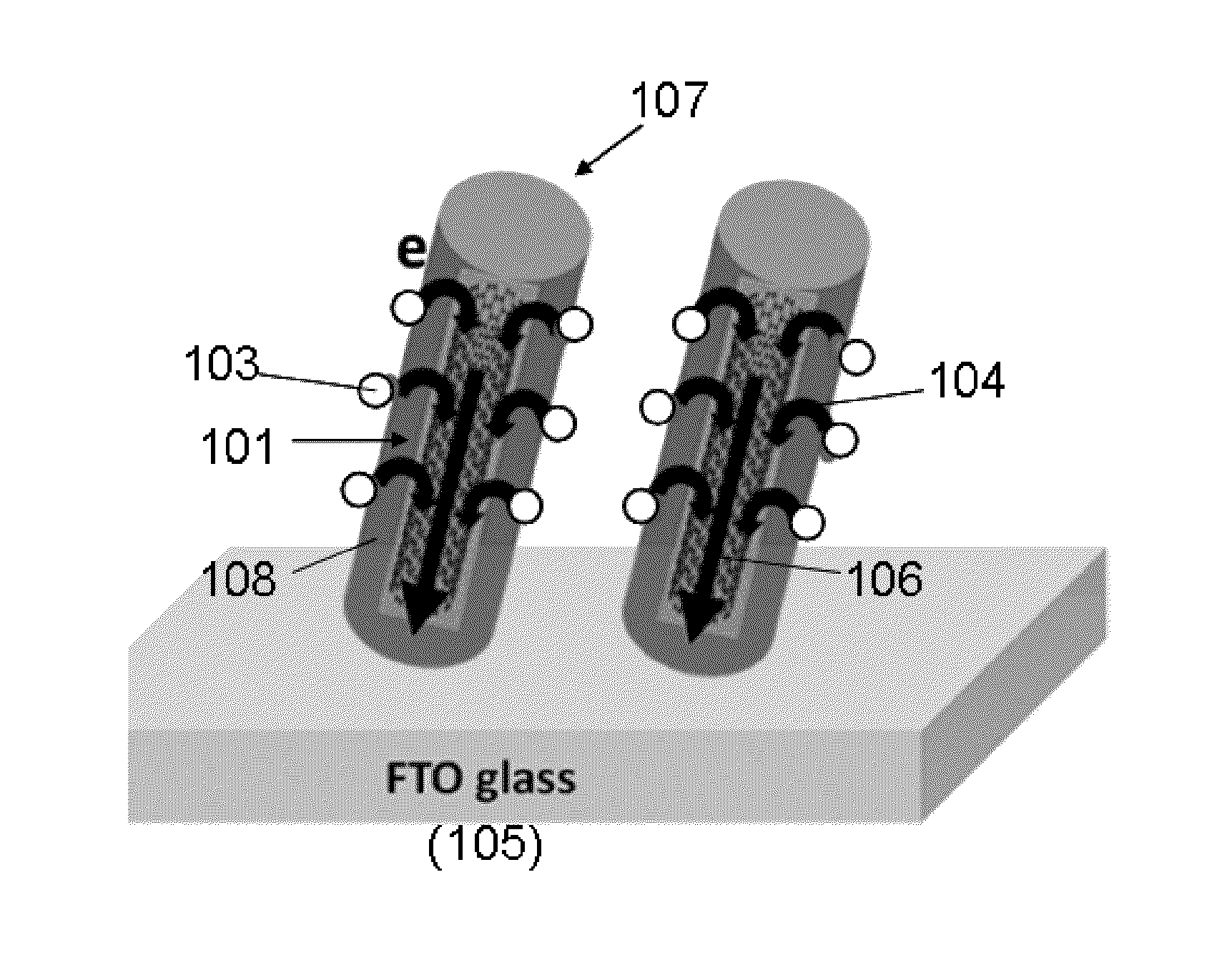
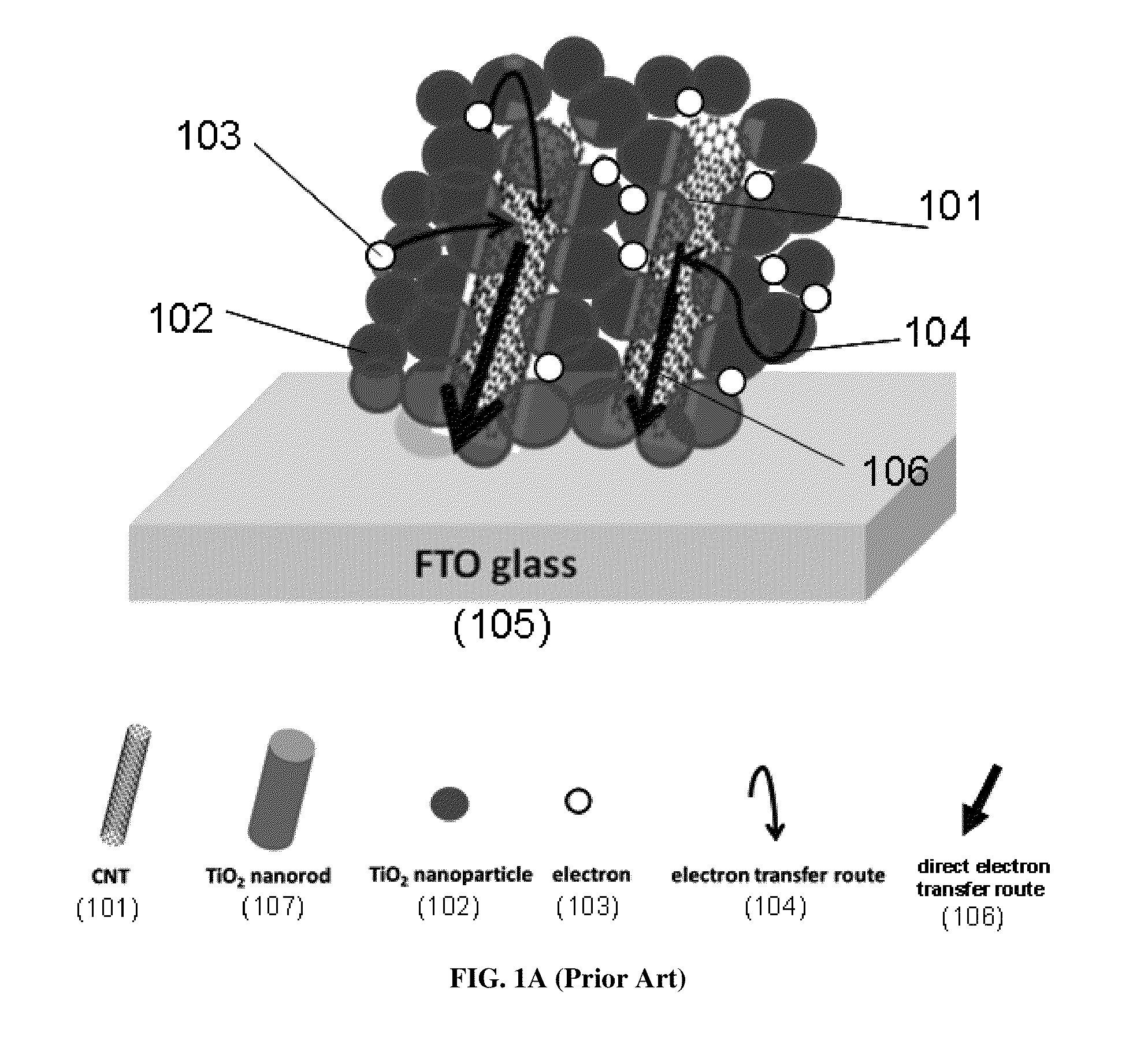
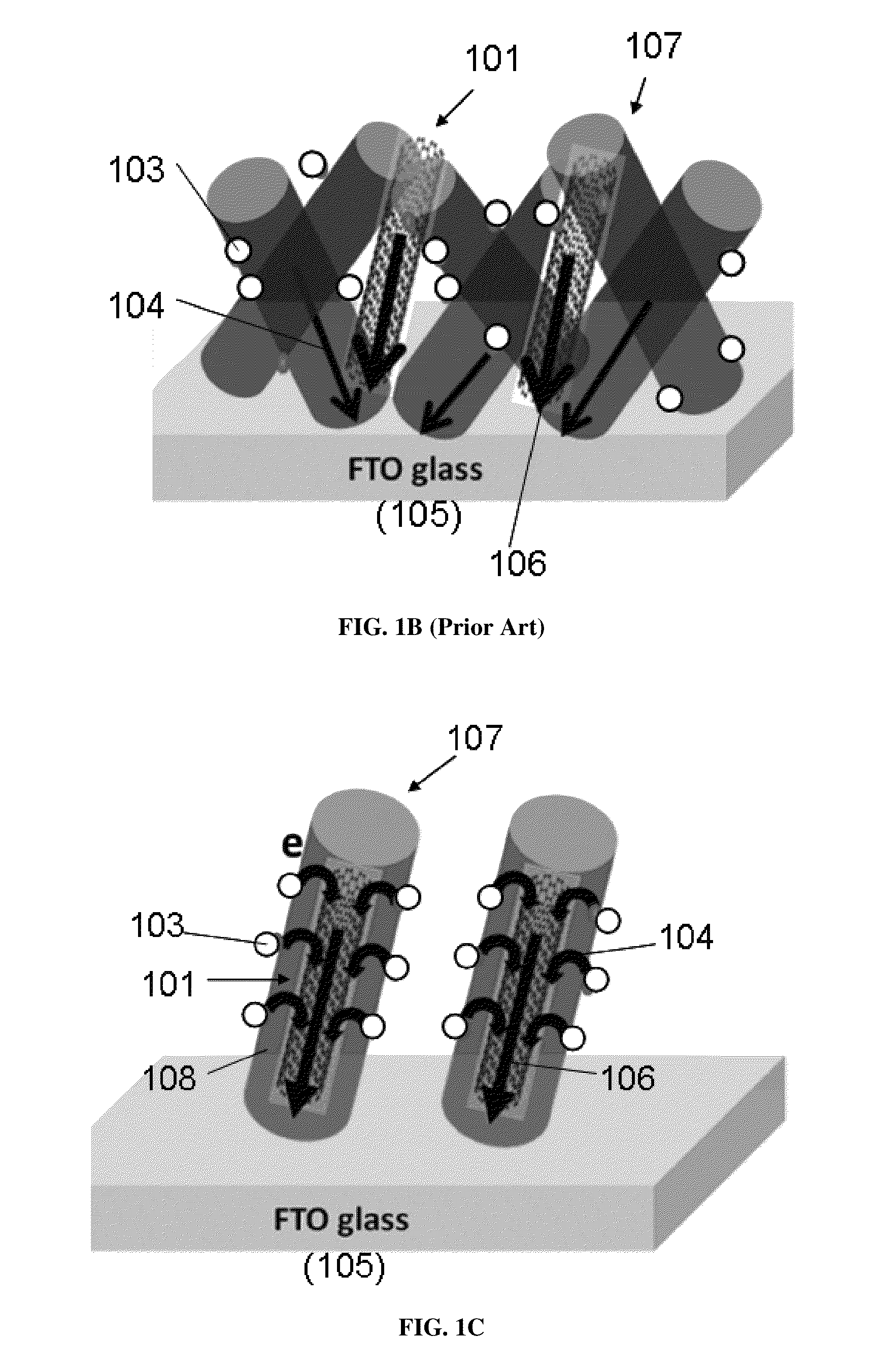
[0069]TiO2 / PVP / MWCNT composite nanofibers were first electrospun on fluorine doped tin oxide (FTO) glass (15Ω per square) from a precursor solution that contained titanium isopropoxide (TIP, 4 g), polyvinylpyrrolidone (PVP, 3.5 g), acetic acid (2 g), MWCNT (0.05˜0.15 g) and ethanol (100 mL). All materials were obtained from Sigma-Aldrich and used without further purification. The voltage of 70 kV was applied over a collector distance of 19 cm. A layer of TiO2 / MWCNT nanorods was peeled off from the original FTO glass after calcination and then transferred to another FTO glass with an ultra-thin adhesive TiO2 paste. The TiO2 / MWCNT nanorod photoanode was obtained after calcinating at 450° C. for 2 h. The corresponding temperature rise rate was 1° C. / min until reaching the calcination temperature of 450° C. The thickness of the photoanode was measured by a surface profiler (TENCOR P-10).

[0070]Before sensitization, the photoanode (3 mm×3 mm) was first treated with an aqueous solution of ...

example 2

[0086]Similar to the experimental conditions of Example 1, the electrospun nanofibers were calcinated at the final temperature of 550° C. (for 2 h) instead of the optimal 450° C. as used in Example 1. Accordingly, three tests were carried out at 550° C. with a rate change in temperature of 1° C. / min, and with 0.1% wt MWCNTs in precursor solution Three samples A-C were obtained. It was expected that more rutile phase was found in the TiO2 nanofibers, which were unfavorable for the solar cell. Indeed, as shown on Table 3, tests on these samples A-C reveal lower fill factor less than 70% with exception of sample B, and lower short circuit density current (Jsc) falling short of 12 mAcm−2. The highest power conversion efficiency (PCE) corresponds to 5.54% which is only half of 10.24% obtained at the optimal condition with the final calcination temperature of 450° C.

TABLE 3VocJscFFPCESample[V][mAcm−2][%][%]A0.707.2161.823.12B0.7210.573.285.54C0.725.0863.152.31

example 3

[0087]After confirming the preferred optimal calcination temperature of 450° C. by keeping the rate of temperature change at 1° C. / min, additional tests were made at 450° C. but with the rate of temperature change increased to 3° C. / min. Four tests were carried out at 450° C. with a rate change in temperature of 3° C. / min, and with 0.1% wt MWCNTs in precursor solution. Four samples D-G were obtained. Firstly, the photoanodes (or composites) were observed to have cracks due to too rapid change in the oven temperature. The cracks in photoanodes are detrimental to performance of the solar cells. Indeed, Table 4 shows disappointing PCE less than 2.5% and much lower Jsc of less than 5.5 mAcm−2 despite the final calcination temperature being at the optimal value of 450° C.

TABLE 4ThicknessVocJscFFPCESample[μm][V][mAcm−2][%][%]D2.20.733.63591.56E16.90.715.47642.48F13.50.693.64471.19G6.50.704.28641.91

[0088]To conclude, workable DSSC cell can be produced with calcinations temperature between ...


PUM


Abstract

The presently claimed invention provides a highly conductive composite used for electric charge transport, and a method for fabricating said composite. The composite comprises a plurality of one-dimensional semiconductor nanocomposites and highly conductive nanostructures, and the highly conductive nanostructures are incorporated into each of the one-dimensional semiconductor nanocomposite. The composite is able to provide fast electric charge transport, and reduce the rate of electron-hole recombination, ultimately increasing the power conversion efficiency for use in solar cell; provide fast electrons transport, storage of electrons and large surface area for adsorption and reaction sites of active molecular species taking part in photocatalytic reaction; enhance the sensitivity of a surface for biological and chemical sensing purposes for use in biological and chemical sensors; and lower the impedance and increase the charge storage capacity of a lithium-ion battery.

Description

CROSS REFERENCE TO RELATED APPLICATION[0001]Pursuant to 35 U.S.C. §119(e), this is a non-provisional patent application which claims benefit from U.S. provisional patent application Ser. No. 61 / 735,068 filed Dec. 10, 2012, and the disclosure of which is incorporated herein by reference.COPYRIGHT NOTICE[0002]A portion of the disclosure of this patent document contains material, which is subject to copyright protection. The copyright owner has no objection to the facsimile reproduction by anyone of the patent document or the patent disclosure, as it appears in the Patent and Trademark Office patent file or records, but otherwise reserves all copyright rights whatsoever.FIELD OF THE INVENTION[0003]The present invention relates to a nanocomposite, and particularly relates to a carbon-based nanocomposite. The present invention also relates to a preparation method for forming said nanocomposite to improve functional applications.BACKGROUND[0004]There is a never ending search for advanced ...

Claims


Application Information

Patent Timeline
IPC IPC(8): H01L29/06H01L21/02
CPCH01L21/02422H01L21/02444H01L21/02513H01L21/02565H01L21/02628B82Y10/00H01L29/127H01L29/0673H01L29/0676H01L29/1606H01M4/131H01M4/485H01M10/052B82Y30/00H01M4/366H01L29/0669H01L21/02606Y10S977/844Y10S977/932Y02E60/10H10K85/221H10K10/488B82Y99/00H01L31/035218H01L31/035227H01M4/666
Inventor LEUNG, WALLACE WOON-FONGYANG, LIJUN
Owner THE HONG KONG POLYTECHNIC UNIV
Why Eureka
Try Eureka