Methods for processing alloys

Active Publication Date: 2014-08-28
ATI PROPERTIES LLC
View PDF4 Cites 28 Cited by
  • Summary
  • Abstract
  • Description
  • Claims
  • Application Information

AI Technical Summary

Benefits of technology

[0008]According to one non-limiting aspect of the present disclosure, a method of processing a workpiece to inhibit precipitation of intermetallic compounds comprises at least one of thermomechanically working and cooling a workpiece including an austenitic alloy. During the at least one of thermomechanically working and cooling the workpiece, the austenitic alloy is at temperatures in a temperature range spanning a temperature just less than a calculated sigma solvus temperature of the austenitic alloy down to a cooling temperature for a time period no greater than a critical cooling time. The calculated sigma solvus temperature is a function of the composition of the austenitic all

Problems solved by technology

Metal alloy parts used in chemical processing facilities may be in contact with highly corrosive and/or erosive compounds under demanding conditions.
These conditions may subject metal alloy parts to high stresses and aggressively promote corrosion and erosion, for example.
If it is necessary to replace damaged, worn, or corroded metallic parts of chemical processing equipment, it may be necessary to suspend facility operations for a period of time.
Similarly, in oil and gas drilling operations, drill string components may degrade due to mechanical, chemical, and/or environmental conditions.
The drill string components may be subject to impact, abrasion, friction, heat, wear, erosion, corrosion, and/or deposits.
Conventional alloys may suffer from one or more limitations that impact their utility as drill string components.
For example, conventional materials may lack sufficient mechanical properties (for example, yield strength, tensile strength, and/or fatigue strength), possess insufficie

Method used


Image

  • Methods for processing alloys
  • Methods for processing alloys
  • Methods for processing alloys

Examples


example 1

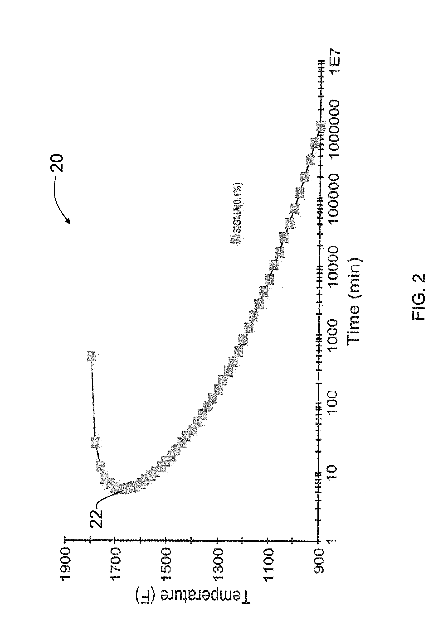
[0108]FIG. 6 shows an example of a TTT diagram 80 for an alloy that has a relatively short allowable critical cooling time as calculated using Equation 3 of the present disclosure. The chemical composition of the alloy that is the subject of FIG. 6 includes, in weight percentages: 26.04 iron; 33.94 nickel; 22.88 chromium; 6.35 molybdenum; 4.5 manganese; 3.35 cobalt; 1.06 tungsten; 1.15 copper; 0.01 niobium; 0.26 silicon; 0.04 vanadium; 0.019 carbon; 0.386 nitrogen; 0.015 phosphorus; and 0.0004 sulfur. For this alloy composition, the calculated sigma solvus temperature 82 calculated according to Equation 1 of the present disclosure is about 1859° F.; the cooling temperature 84 calculated according to Equation 2 of the present disclosure is about 1665° F.; and the critical cooling time 86 calculated according to Equation 3 of the present disclosure is about 7.5 minutes. According the present disclosure, in order to prevent precipitation of the deleterious intermetallic phase, the work...

example 2

[0110]FIG. 8 shows an example of a TTT diagram 90 for an alloy that has a longer critical cooling time calculated using Equation 3 than the alloy of FIG. 6. The chemical composition of the alloy of FIG. 8 comprises, in weight percentages: 39.78 iron; 25.43 nickel; 20.91 chromium; 4.78 molybdenum; 4.47 manganese; 2.06 cobalt; 0.64 tungsten; 1.27 copper; 0.01 niobium; 0.24 silicon; 0.04 vanadium; 0.0070 carbon; 0.37 nitrogen; 0.015 phosphorus; and 0.0004 sulfur. The calculated sigma solvus temperature 92 for the alloy calculated according to Equation 1 is about 1634° F.; the cooling temperature 94 calculated according to Equation 2 is about 1556° F.; and the critical cooling time 96 calculated according to Equation 3 disclosure is about 28.3 minutes. According the method of the present disclosure, in order to prevent precipitation of the deleterious intermetallic phase within the alloy, the alloy must be formed and cooled when in the temperature range spanning a temperature just below...

example 3

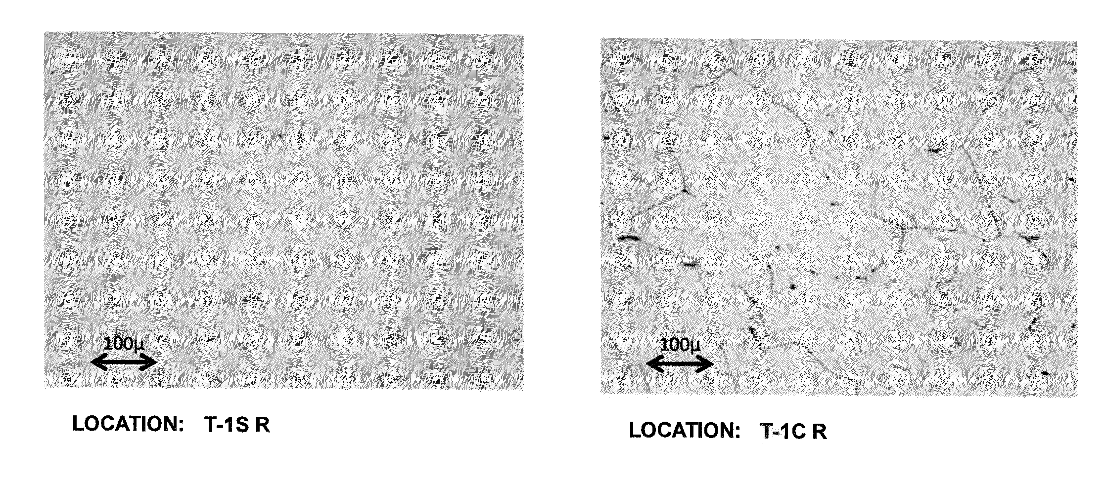
[0112]Samples of the non-magnetic austenitic alloy of heat number 49FJ (see Table 1) were provided. The alloy had a calculated sigma solvus temperature calculated according to Equation 1 of 1694° F. The alloy's cooling temperature calculated according to Equation 2 was 1600° F. The time to the nose of the C curve the TTT diagram (i.e., the critical cooling time) calculated according to Equation 3 was 15.6 minutes. The alloy samples were annealed at 1950° F. for 0.5 hours. The annealed samples were placed in a gradient furnace with the back wall of the furnace at approximately 1600° F., the front wall of the furnace at approximately 1000° F., and a gradient of intermediate temperatures within the furnace between the front and back wall. The temperature gradient in the furnace is reflected in the plot depicted in FIG. 10. The samples were placed at locations within the furnace so as to be subjected to temperatures of 1080° F., 1200° F., 1300° F., 1400° F., 1500° F., or 1550° F., and w...


PUM

PropertyMeasurementUnit
Temperatureaaaaaaaaaa
Percent by massaaaaaaaaaa

Abstract

A method of processing a workpiece to inhibit precipitation of intermetallic compounds includes at least one of thermomechanically processing and cooling a workpiece including an austenitic alloy. During the at least one of thermomechanically working and cooling the workpiece, the austenitic alloy is at temperatures in a temperature range spanning a temperature just less than a calculated sigma solvus temperature of the austenitic alloy down to a cooling temperature for a time no greater than a critical cooling time.

Description

BACKGROUND OF THE TECHNOLOGY[0001]1. Field of the Technology[0002]The present disclosure relates to methods of alloys. The present methods may find application in, for example, and without limitation, the chemical, mining, oil, and gas industries.[0003]2. Description of the Background of the Technology[0004]Metal alloy parts used in chemical processing facilities may be in contact with highly corrosive and / or erosive compounds under demanding conditions. These conditions may subject metal alloy parts to high stresses and aggressively promote corrosion and erosion, for example. If it is necessary to replace damaged, worn, or corroded metallic parts of chemical processing equipment, it may be necessary to suspend facility operations for a period of time. Therefore, extending the useful service life of metal alloy parts used in chemical processing facilities can reduce product cost. Service life may be extended, for example, by improving mechanical properties and / or corrosion resistanc...

Claims


Application Information

Patent Timeline
IPC IPC(8): C22F1/10C21D8/00
CPCC21D8/005C22F1/10C21D11/005C22C38/001C22C38/005C22C38/42C22C38/44C22C38/46C22C38/48C22C38/50C22C38/52C22C38/58C21D6/004C21D6/005C21D6/007C21D2211/001C21D8/00C21D11/00C22C38/54
Inventor FORBES JONES, ROBIN M.MCDEVITT, ERIN T.
Owner ATI PROPERTIES LLC
Why Eureka
Try Eureka