High temperature resistant polysulfone insulation for pipe

a polysulfone and pipe technology, applied in the field of polymer compositions, can solve the problems of reducing or losing production, affecting the value of assets, and requiring the replacement of pipeline sections or entire systems with corresponding loss of asset valu

Inactive Publication Date: 2014-10-23
SHAWCOR LTD
View PDF4 Cites 29 Cited by
  • Summary
  • Abstract
  • Description
  • Claims
  • Application Information

AI Technical Summary

Benefits of technology

[0014]According to an embodiment, there is provided an insulated high-temperature transport conduit for use in offshore, deep water environments, the conduit comprising: (a) a continuous steel pipe made up of one or more pipe sections, wherein the steel pipe has an outer surface and an inner surface; (b) a corrosion protec

Problems solved by technology

Both of these phenomena are related to the temperature of the fluid, and in extreme cases the conduit can become severely constricted or even blocked.
This in turn can lead to reduced or lost production.
In particularly serious cases this may lead to the need to replace sections of pipeline or entire systems with corresponding loss of asset value.
Hence, the traditional thermal insulation foam technology used in shallow waters and the associated design and test methodologies may not be applicable to deep-water projects.
In cases of long pipe tiebacks, for example subsea-to-beach tiebacks, and in cases where the service temperature is above approximately 150° C., there exist limitations with current technology that may hinder the successful development of offshore, deep water oil or gas field

Method used


Image

  • High temperature resistant polysulfone insulation for pipe
  • High temperature resistant polysulfone insulation for pipe
  • High temperature resistant polysulfone insulation for pipe

Examples


example 1

Thermal Conductivity Testing

[0169]Thermal conductivity testing was performed on two identical samples of polyphenylsulfone (Samples 1 and 2) at temperatures of 30° C., 90° C., 120° C., 150° C. and 190° C. The thermal conductivity of each sample was tested in accordance with ASTM Standard C518-04: “Standard Test Method for Steady-State Thermal Transmission Properties by Means of the Heat Flow Meter Apparatus”. Samples 1 and 2 each had a thickness of 5.96 mm and diameter of 57.73 mm. The results of the thermal conductivity testing of Example 1 are shown in Table 2 below, and in FIG. 4.

example 2

Thermal Conductivity Testing

[0170]Thermal conductivity testing was performed on two identical samples of polyphenylsulfone (Samples 3 and 4) at temperatures of 30° C., 90° C., 120° C., 150° C. and 200° C. Samples 1 to 4 all had the same composition. The results of the thermal conductivity testing of Example 2 are shown in Table 2 below, and in FIG. 5.

TABLE 2Thermal Conductivity (W / m · K)Temperature (° C.)Sample 1Sample 2Samples 3, 4300.2330.2120.246900.2510.2570.2651200.2580.2630.2741500.2640.2670.2801900.2410.254NA200NANA0.297

example 3

Long-Term Heat Flow Testing

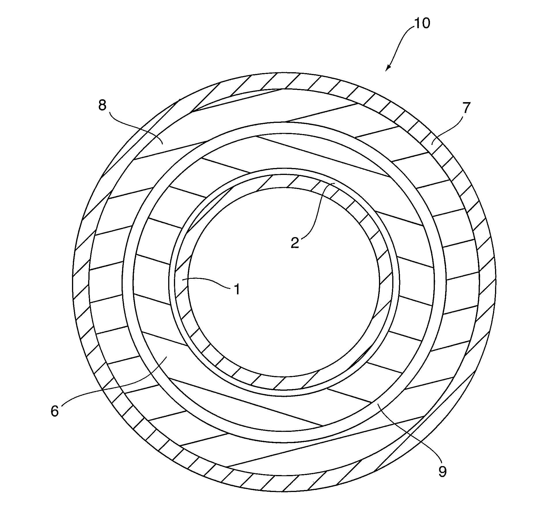
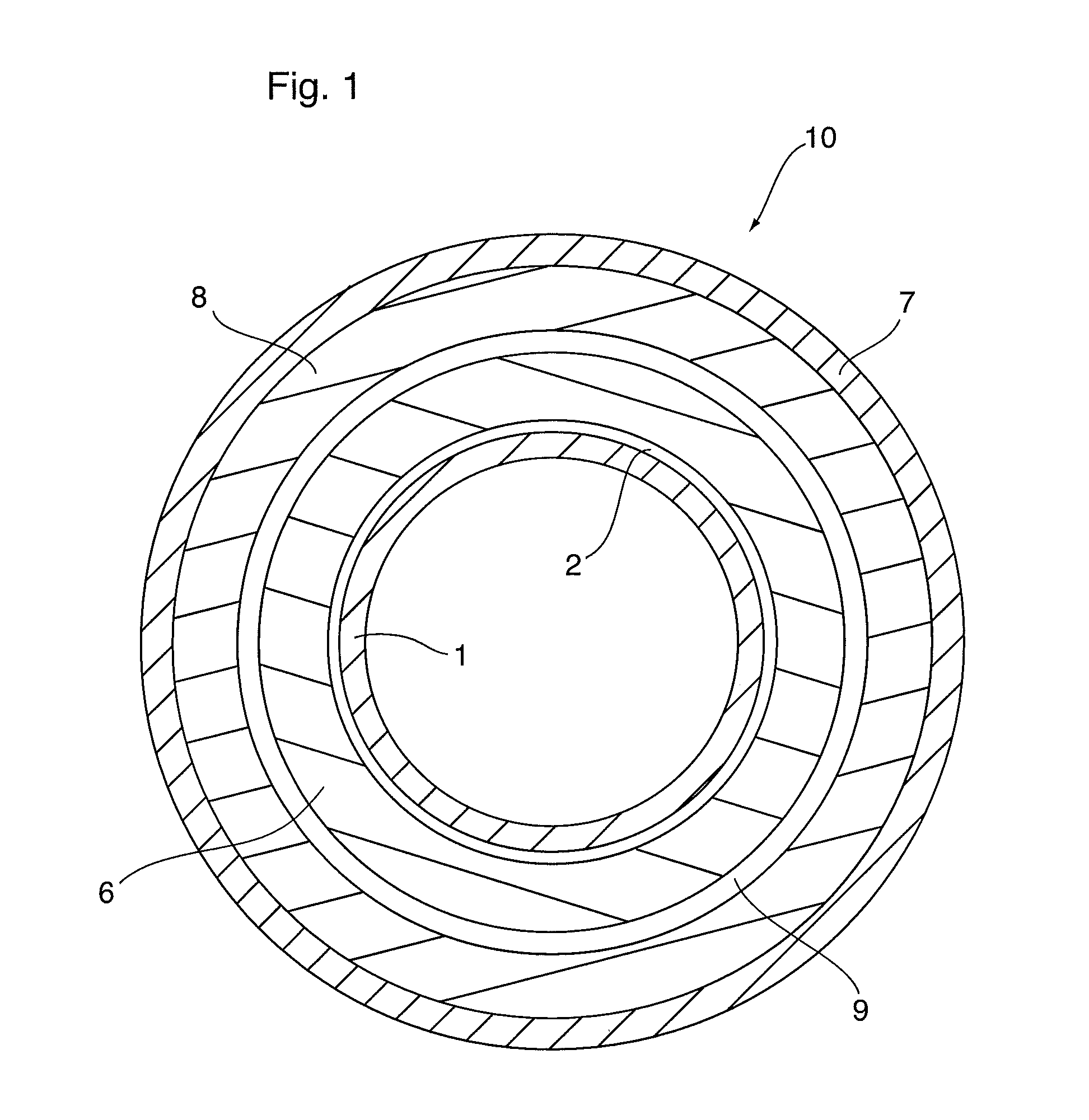
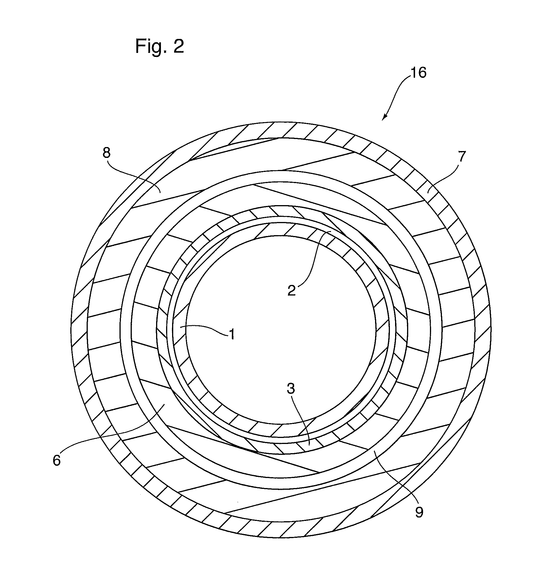
[0171]Long-term heat flow testing at 205° C. was conducted in order to test the effectiveness and the stability of the insulation system. The test samples consisted of three layers, a steel plate to simulate a pipe; a first thermal insulation layer comprised of polyphenylsulfone, and a second thermal insulation layer comprised of a high impact polystyrene. The steel plate was heated to simulate hot fluid flowing through a pipe; and the outer surface of the second thermal insulation layer was in contact with cold water to simulate a subsea environment. The results of the testing are shown in FIG. 6, in which:[0172]1 represents the temperature of the water in contact with the outer surface of the second thermal insulation layer;[0173]2 represents the temperature of the outer surface of the second thermal insulation layer;[0174]3 represents the Q value, representing heat flow through the two insulation layers; and[0175]4 represents the temperature of the stee...


PUM

PropertyMeasurementUnit
Temperatureaaaaaaaaaa

Abstract

A polymeric composition for insulating fluid and/or gas transport conduits, such as off-shore oil and gas pipelines operating at temperatures of about 200° C. or higher in water depths above 1,000 metres. The outer surface of the conduit is provided with at least one layer of solid or foam insulation comprising a high temperature resistant polysulfone having sulfone, ether and isopropylidene bridging groups, and/or a polyphenylsulfone or a polyethersulfone.

Description

CROSS-REFERENCE TO RELATED APPLICATION[0001]This application claims priority to and the benefit of U.S. Provisional Patent Application No. 61 / 770,557 filed Feb. 28, 2013, the contents of which are incorporated herein by reference.FIELD OF THE INVENTION[0002]The present invention relates to polymeric compositions for insulating fluid and / or gas transport conduits, transport conduits insulated with these compositions, and methods for the production and application thereof. More particularly, the polymeric compositions according to the invention comprise high temperature resistant polysulfone thermoplastics having low thermal conductivity, high thermal softening point and high compressive creep resistance for use in the thermal insulation of fluid and / or gas transport conduits such as oil and gas pipelines.BACKGROUND OF THE INVENTION[0003]There is increasing demand in the oil and gas industry for higher performance thermal coatings to insulate and protect off-shore transport conduits o...

Claims


Application Information

Patent Timeline
IPC IPC(8): F16L9/14B29C48/09B29C48/151B29C48/21B29C48/385B29C48/40
CPCF16L9/14B32B1/08F16L58/1054F16L58/181F16L59/143F16L59/20F16L13/0272B29C63/10B29C44/24B29C44/324B32B7/12B32B27/065B32B27/08B32B27/302B32B27/32B32B2266/025B32B2307/302B32B2307/304B32B2307/4026B32B2307/558B32B2307/714B32B2597/00B29C48/09B29C48/0021B29C48/151B29C48/21B29C48/385Y10T29/49888B29C48/40
Inventor EDMONDSON, STEPHEN J.WONG, DENNISMOCKEL, MARCOS
Owner SHAWCOR LTD
Why Eureka
Try Eureka