1) Drift Time IMS (DT-IMS)6 is one of the best known mobility techniques, perhaps due to its simplicity, robustness, speed, and relatively small size and
power consumption. DT-IMS are mostly used for military and security purposes, although they are also used in other industries as well as in many new areas of research including
proteomics and
structural biology8-11. The resolving power of DTIMS (R) is mainly limited by Brownian
diffusion; classic DT-IMS can reach R=100, but their sensitivity is limited by a low
duty cycle. Nevertheless, their transmission can be improved by the use of ion funnels12,
multiplexing and ion accumulation13. Resolving powers higher than 300, and approaching 400, were achieved with the so-called High-Resolution
Ion Cyclotron Mobilityl14,15. The pulsed input and output of DT-IMS might be advantageous if the
ion source is also pulsed, but it usually hinders transmission and complicates the interfaces in tandem schemes, such as IMS-MS, and with other continuous ion sources such as electro-spray (ESI).
2) Travelling Wave IMS (TW-IMS): Its separation mechanism allows for true mobility separation, but in practice it also produces pulsed packets of ions and, what is more serious, the reliability of the structural information obtained is unclear because: (i) in the intense electrical fields required, ion heating can have a significant effect16, and (ii) drift time is related to the mobility in a complicated way, which is still not completely understood17,18.
3) Field Asymmetric IMS (FAIMS)19-22, also termed Differential Mobility Spectrometry (DMS), is an alternative and robust technique that separates ions in space rather than in time, thus producing a
continuous flow of selected ions with a 100%
duty cycle. FAIMS separates ions according to nonlinearities in the mobility arising in strong fields23-25, and traditionally produced relatively poor resolving powers (near 20). Nevertheless, recent developments26-29 have shown that the separation capability can be dramatically increased by adding polar dopants to the drifting gas. Shvartsburg and Smith30 also reached resolving powers exceeding 200 by increasing the time of
residence of ions within the filter. The new generation of DMS-MS commercialized as ‘SelexIon’ is a powerful tool to reduce background levels31, and allows mobility selection before ions pass through the
Atmospheric Pressure Ionization (API) interface32, which permits the incorporation of the IMS by a relatively simple
upgrade of the MS (if compared with TW-IMS that require low pressures), but it does not provide clearly interpretable structural information.
4) Differential
Mobility Analysis (DMA) provides absolute
mobility analysis, and also produces a continuous output of mobility-selected ions. Planar DMAs33 permit
coupling with virtually any API-MS33 and provide an improved transmission of ions. The mobility is measured at moderated ionic temperatures with little fragmentation, which makes structural interpretation of the data easier34-37. However, DMAs require a flow with high speed and high Reynolds numbers (Re) that is prone to turbulence38.
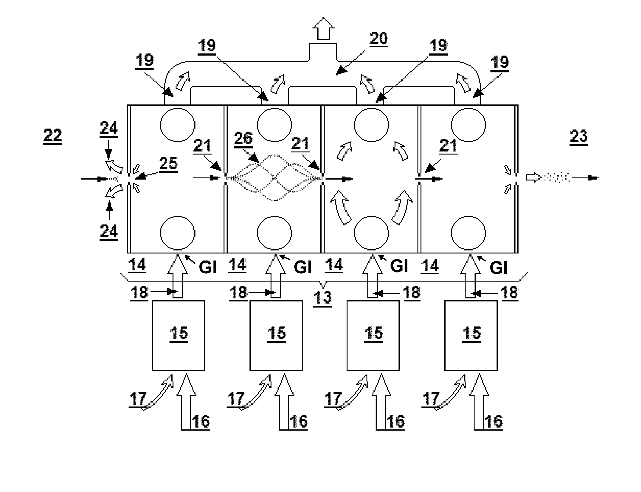
5) Variable
Electric Field Mobility Analysis (VEFMA) US 20100243883 A1 also provides a continuous output of mobility selected ions. Ions are separated according to their true mobility using only electric fields. The selected ions coalesce at the analyzer outlet while other ions are deflected away and not transferred. Ions are separated in space and thus a
continuous flow of filtered ions with a
narrow range of selected mobility ions is produced, as in Differential Mobility Analyzers (DMAs); yet no high fluid velocity field is required, thus avoiding the limitations in DMAs associated with flow unsteadiness, and turbulent transition. VEFMA is at present the only technology capable of: (i) producing a continuous output of mobility selected ions, (ii) operating at
ambient pressure, (these two aspects are essential for the Add-on architectural capability), (iii) selecting the ions according to their absolute mobility, and (iv) being able to operate in transparent mode (i.e. allowing ions of all mobilities to pass though the outlet of the analyzer without being mobility selected).
The use of pulsated output IMS analysis techniques (namely DTIMS and TWIMS) for IMS-IMS analysis has two main problems:i) the
duty cycle of each stage is usually very low (around 1%), and the duty cycle of the composed architecture tends to be even lower (1% times 1%=10−4), and this low duty cycle reduces the sensitivity of the analyzers.ii)
Coupling the two pulsed IMS stages requires a complicated synchronization to gate the desired pulse of ions in the second stage at the time when they arrive at the outlet of the first stage, which is not known a priori.
However, when the filtering parameters of each DMA are not known a priori, which is a very common circumstance if the operator wishes to identify these variables, or if the operator wishes to re-calibrate the instrument, all the DMA stages must be scanned together in a multi-dimensional spectrum because they cannot operate in transparent mode, and this scan can be very
time consuming.
The time required to identify the position of the peaks in a DMA-DMA-
quadrupole architecture would be simply prohibitive (approximately three weeks).
For instance, the architecture can be used in an explosive
detector, for which the filtering parameters are not expected to change (aside from
fine tuning), but these high times become a real problem if the architecture is to be used in a more
general purpose platform for which identification of the filtrating parameters can be a regular procedure.
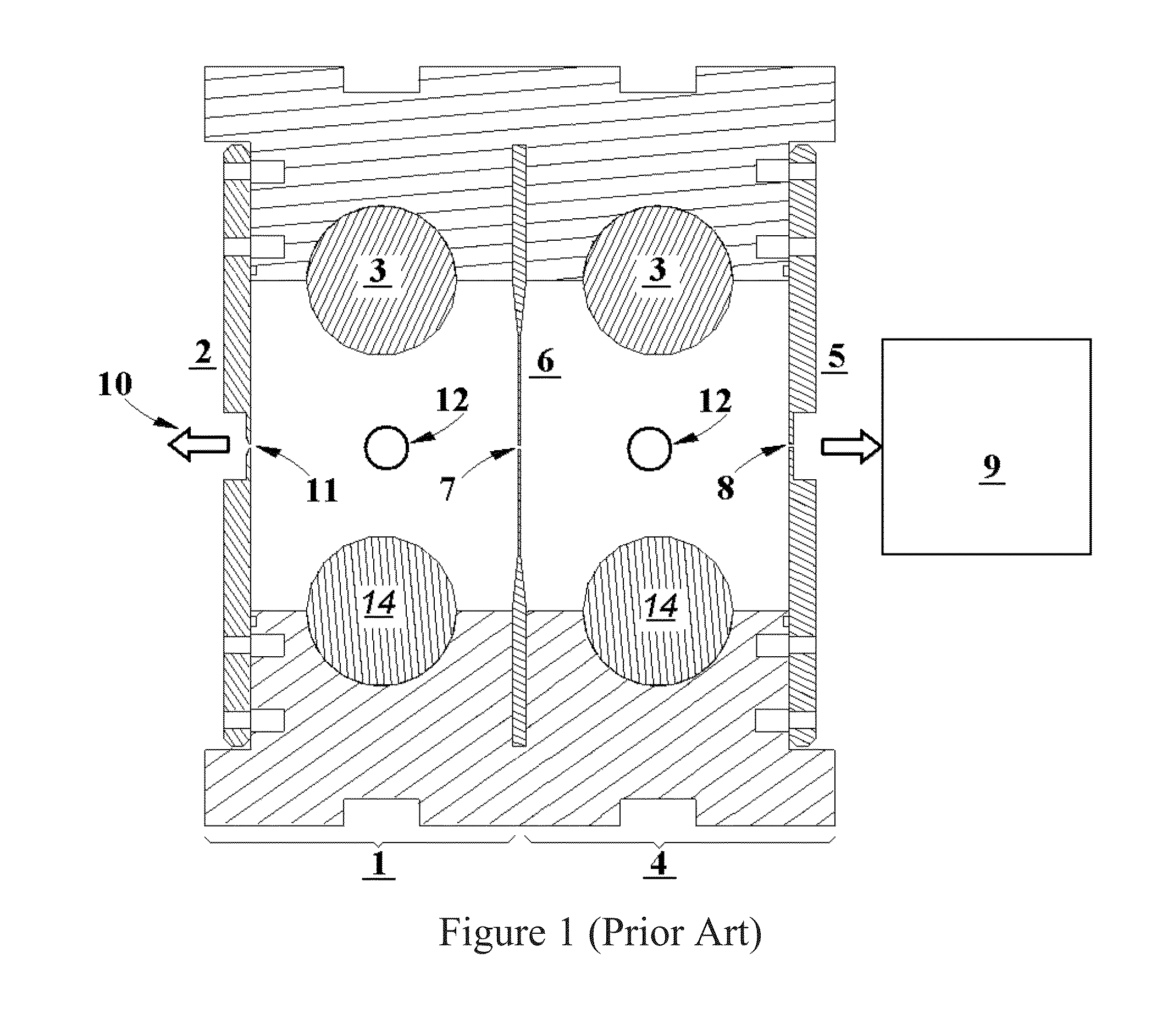
The invention described in U.S. Pat. No. 7,855,360 and in U.S. Pat. No. 8,278,622 also has the problem that transmission of ions between one DMA and the next is very poor.
Each DMA requires a laminar and high speed flow (with high Reynolds and
high pressure gradients) to separate the ions, and these flows are very delicate because they easily become turbulent due to their high Reynolds.
However, the strong pressure gradients produced by the high speed flow tend to deform the inner walls of the DMA, and these deformations affect the boundary layer of the flow, which might easily become turbulent, thus destroying the resolving power of the DMA.
However, if the
rigid structure of US 20080251714 is used in combination with the tandem DMA-DMA architectures proposed in U.S. Pat. No. 7,855,360 and in U.S. Pat. No. 8,278,622, then the transmission of ions would be very poor for two main reasons:(i) in a tandem DMA-DMA scheme, the
local pressure gradient that pushes the gas and the ions from one DMA to the next cannot be very high, because the flow of incoming gas and ions that pass from one DMA to the next would otherwise form a jet in the second DMA that would perturb the high Reynolds flow of the second DMA, which would become turbulent, and which would thus have a very poor resolving power and a poor transmission.
As a results, ions have to be transnsported from one DMA to the next at low velocities, for which diffusional losses dominate.(ii) the need for thick and rigid structures in each DMA inevitably requires a
thick wall between each DMA, which must be crossed by the slit that allows for the passage of ions from one DMA to the next, resulting in a long time of
residence of the ions through these slits.
These long slits (the slits are long along the direction of the movement of the ions through the slit) also impede the passage of electric fields, which cannot be used to push the ions forward.
As a result, the ion losses in the channel that communicates one DMA with the next are very high.
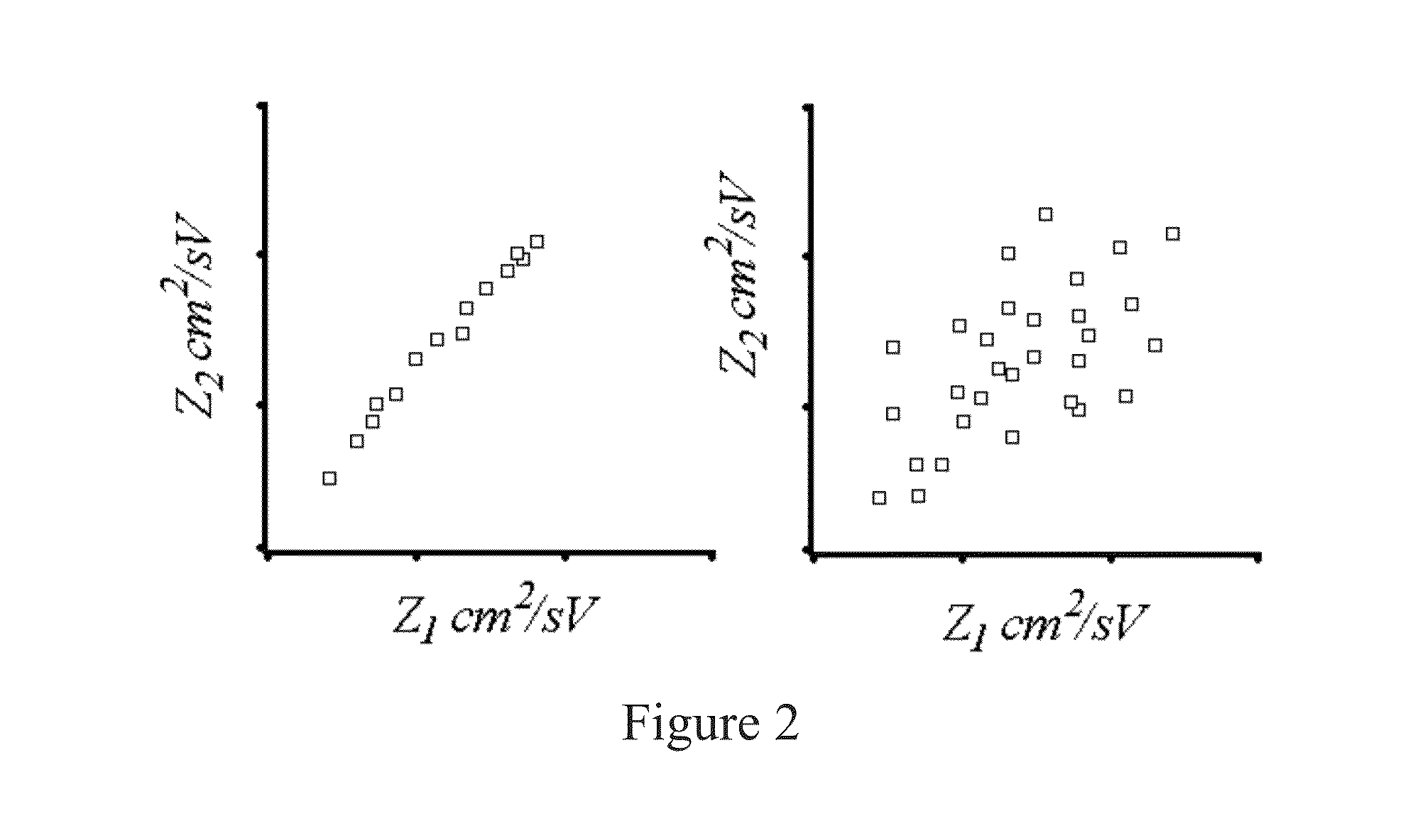
As a result, two different type of ions, which have the same mobility in the first stage, and which thus pass together through the first stage at a given mobility (not being differentiated in the first stage), cannot be differentiated in the second stage because their mobilities in the second stage are also very similar, meaning that the separation capacity of the analyzer is poor.
While these approaches increase the separation capacity, they have a poor transmission of selected ions.
This poor transmission is mainly caused due to losses of ions in the required ion modification stage.
In order to maximize the transmission, it is desirable to pass the ions directly from the
one stage to the next, but this scheme would not provide enough space for the required modification
cell.
However, experimental data shows that the mobility in the different gases (N2, CO2, SF6) is poorly orthogonal.
The orthogonality of the measurements in US 20100243883 A1 is poor, and hence the separation capacity of the tandem IMS-IMS analysis is also poor.
As a result, the composition of the gasses in each stage is an uncontrolled mixture of different gasses initially introduced each stage, thus leading to non repeatable and difficult to interpret results.
Note that, in these applications, dopants do not increase the overall separation capacity of the instruments.
In this second case, the introduction of the
dopant would be counterproductive.
And hence, the use of dopants, and the selection of the right
dopant require specific studies for each application, and cannot be used by default in a
general purpose system.
However, there is to our knowledge not a solution to solve this problem.
However, FAIMS do not provide absolute mobility ion selection.
Despite the potential offered by dopants, using them in IMS-IMS applications is very complicated.
As a result of these effects, the concentration of dopants becomes unpredictable and difficult to control.
And hence the mobility varies in an uncontrolled fashion, which makes it impossible to take
advantage of the use of dopants in IMS-IMS schemes.

