Resistance spot welding of steel to pre-coated aluminum

a technology of resistance spot welding and aluminum, which is applied in the direction of welding equipment, welding/soldering/cutting articles, manufacturing tools, etc., can solve the problems of reducing the strength and ductility reducing the mechanical properties of the weld joint, and reducing the melting point, so as to achieve the effect of enhancing the resistance spot weld ability of steel workpieces and aluminum workpieces, and reducing melting points

Active Publication Date: 2014-12-11
GM GLOBAL TECH OPERATIONS LLC
View PDF3 Cites 98 Cited by
  • Summary
  • Abstract
  • Description
  • Claims
  • Application Information

AI Technical Summary

Benefits of technology

[0007]The ability to resistance spot weld a steel workpiece and an aluminum workpiece is enhanced by replacing at least the refractory aluminum oxide-based layer on the faying surface of the aluminum workpiece with a different, protective coating. The substituted protective coating may be a metallic coating that has a lower melting point than that of aluminum (the metal), or it may be a metal oxide conversion coating. Examples of metals that can be employed to make a metallic coating are zinc and tin. Examples of metal oxides that can be found in a metal oxide conversion coating are oxides of titanium, zirconium, chromium, or silicon. The protective coating may be anywhere from about 1 nm to about 10 μm thick depending on the coating type.

Problems solved by technology

Spot welding a steel workpiece to an aluminum workpiece presents some challenges.
These two types of metals have several considerable dissimilarities that tend to disrupt the welding process.
Fe—Al intermetallic compounds, in turn, can reduce the strength and ductility of the weld joint if their growth is excessive.
Such characteristics are not conducive to the mechanics of spot welding a steel workpiece to an aluminum workpiece.
Specifically, the surface oxide layer raises the electrical contact resistance of an aluminum workpiece—namely, at its faying surface and electrode / workpiece contact interface—thus causing excessive heat to be generated at those interfaces making it difficult to effectively concentrate heat within the aluminum workpiece.
Moreover, the problems posed by the refractory oxide layer on the surface of the aluminum workpiece are further complicated by the fact that the oxide layer can self-heal or regenerate if breached in the presence of oxygen.

Method used


Image

  • Resistance spot welding of steel to pre-coated aluminum
  • Resistance spot welding of steel to pre-coated aluminum
  • Resistance spot welding of steel to pre-coated aluminum

Examples


Embodiment Construction

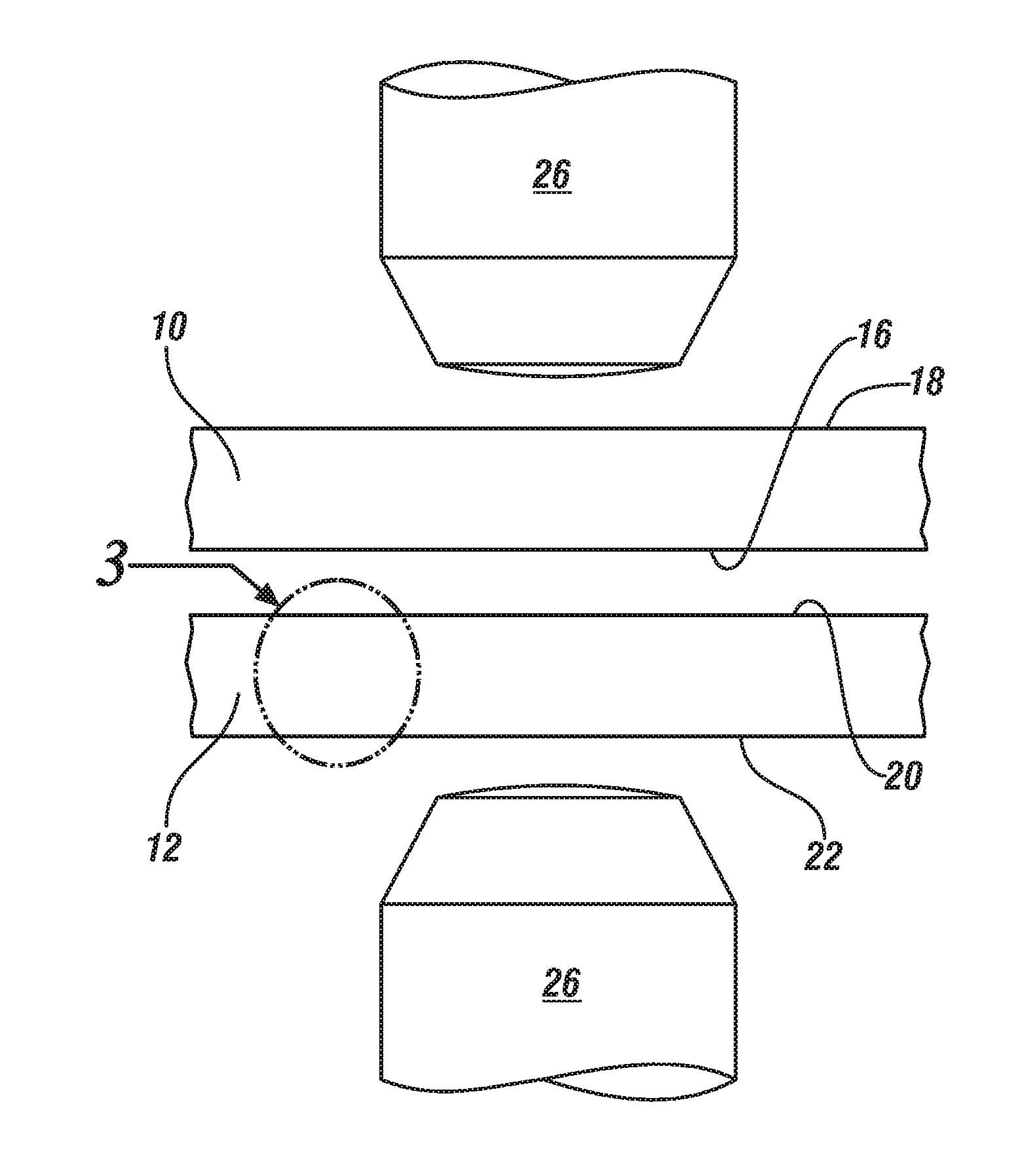
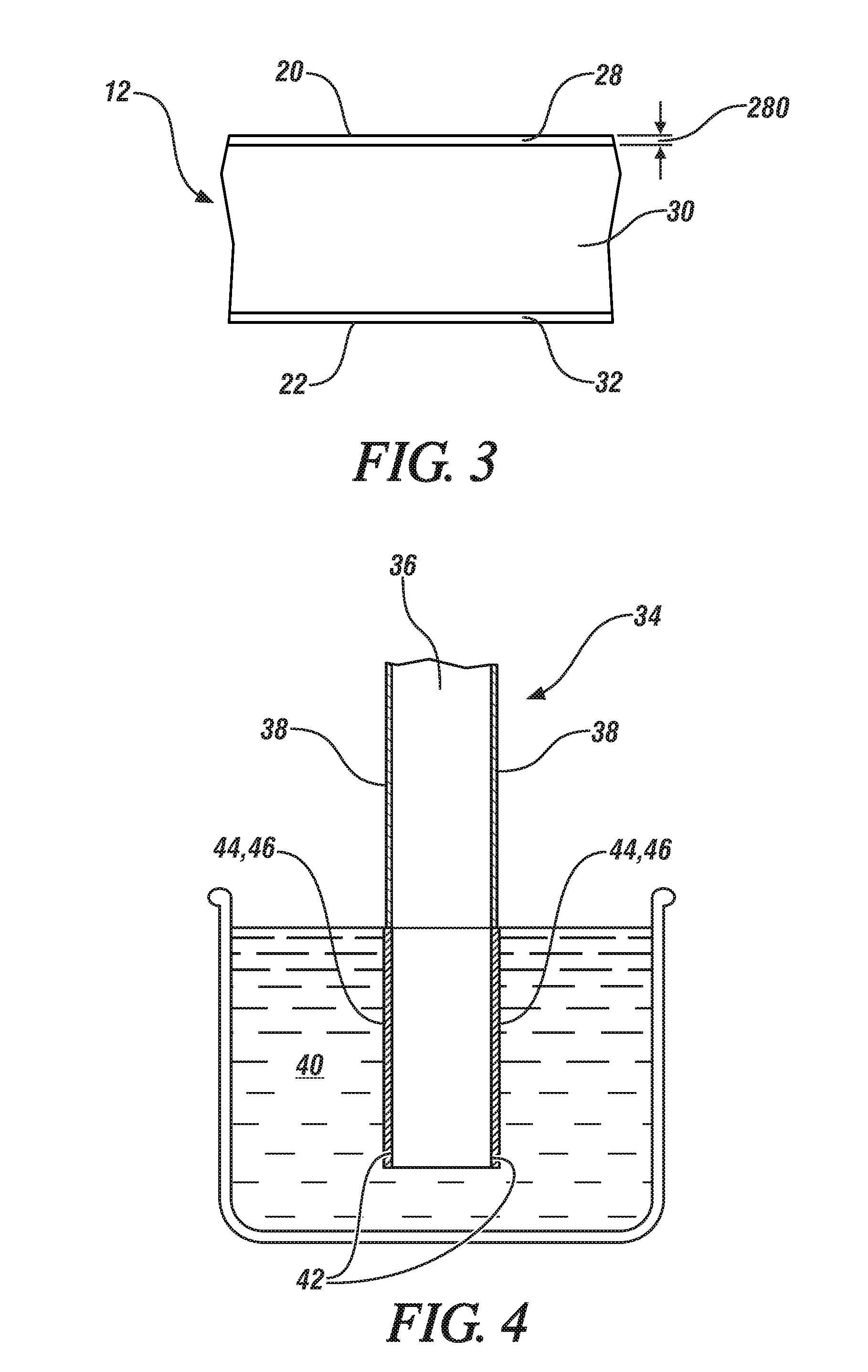
[0020]FIGS. 1-3 generally depict a steel workpiece 10 and an aluminum workpiece 12 that are assembled for resistance spot welding at a predetermined weld site 14. The steel workpiece 10 is preferably a galvanized, or zinc-coated, low carbon steel. Other types of steel workpieces may of course be used including, for example, a low carbon steel or a galvanized advanced high strength steel (AHSS). Some specific types of steels that may be used in the steel workpiece 10 are interstitial-free (IF) steel, dual-phase (DP) steel, transformation-induced plasticity (TRIP) steel, and press-hardened steel (PHS). Regarding the aluminum workpiece 12, it may include an aluminum-magnesium alloy, an aluminum-silicon alloy, an aluminum-magnesium-silicon alloy, an aluminum-zinc alloy, or aluminum metal. Some specific aluminum alloys that may be used in the aluminum workpiece 12 are AA5754 aluminum-magnesium alloy, AA6022 aluminum-magnesium-silicon alloy, and AA7003 aluminum-zinc alloy. The term “workp...


PUM

PropertyMeasurementUnit
thicknessaaaaaaaaaa
melting pointaaaaaaaaaa

Abstract

Resistance spot welding of a steel workpiece to an aluminum or an aluminum alloy workpiece can be facilitated by replacing the refractory aluminum oxide-based layer(s) on at least the faying surface of the aluminum or aluminum alloy workpiece with a protective coating that is more conducive to the spot welding process. The protective coating may be a metallic coating or a metal oxide conversion coating. In a preferred embodiment, the protective coating is a coating of zinc, tin, or an oxide of titanium, zirconium, chromium, or silicon.

Description

[0001]This application claims the benefit of U.S. provisional patent application No. 61 / 832,482, filed on Jun. 7, 2013, the entire contents of which are hereby incorporated by reference.TECHNICAL FIELD[0002]The technical field of this disclosure relates generally to resistance spot welding and, more particularly, to resistance spot welding a steel workpiece to an aluminum or an aluminum alloy workpiece.BACKGROUND[0003]Resistance spot welding is a process used by a number of industries to join together two or more metal workpieces. The automotive industry, for example, often uses resistance spot welding to join together pre-fabricated metal workpieces during the manufacture of a vehicle door, hood, trunk lid, or lift gate, among others. A number of spot welds are typically formed along a peripheral edge of the metal workpieces or some other bonding region to ensure the part is structurally sound. While spot welding has typically been practiced to join together certain similarly-compo...

Claims


Application Information

Patent Timeline
Patent Type & Authority Applications(United States)
IPC IPC(8): B23K11/18B23K11/20B23K11/34B23K11/11
CPCB23K11/115B23K11/34B23K2203/20B23K2103/20
Inventor SIGLER, DAVID R.CARLSON, BLAIR E.ABD ELHAMID, MAHMOUD H.
Owner GM GLOBAL TECH OPERATIONS LLC
Why Eureka
Try Eureka