Modified planar cell (MPC) and electrochemical device battery (stack) based on MPC, manufacturing method for planar cell and battery, and planar cell embodiments

a technology of electrochemical device and planar cell, which is applied in the direction of fuel cell, baking, dough shaping, etc., can solve the problems of affecting the complexity of sealing connection of gas manifolds at the input and output of reagents in the cell and battery, and the inability to estimate specific characteristics without, so as to improve the uniformity and inter-space pressure of reagent feed and increase the packing density. density, the effect o

Inactive Publication Date: 2015-01-01
LIPILIN ALEKSANDR S +1
View PDF2 Cites 2 Cited by
  • Summary
  • Abstract
  • Description
  • Claims
  • Application Information

AI Technical Summary

Benefits of technology

[0045]In this case, the suggested structure ensures uniform gas flow distribution both between the cells and along the electrode surface of each cell.
[0046]The authors also offer the formation method of the structure stated. The suggested structure consists of at least one three-layer film (anode-electrolyte-cathode) for the corrugated electrochemical part of the cell and for its connection to the front and rear wall, and for perforated flat front and rear walls through which one or both reagents are fed. This film is made from electrolyte film or from structural material. At the same time the gas manifold can be arranged either from an upper and lower side of the cell (in case the cells are connected to the batt

Problems solved by technology

In addition, it is impossible to estimate specific characteristics without them, for example, kW/l; kW/kg required for design comparison and determination of their application.
This is because such transformations are accompanied by space variations and disruptions.
Disadvantages of the planar structure analogues and prototypes may be a complexity of the sealed connection of gas manifolds at the input and output of reagents in the cell and battery, and rather long sealed connection seams compared to the operating area (1/S-cm/cm2 or 1/cm).
Since the sealed connectio

Method used


Image

  • Modified planar cell (MPC) and electrochemical device battery (stack) based on MPC, manufacturing method for planar cell and battery, and planar cell embodiments
  • Modified planar cell (MPC) and electrochemical device battery (stack) based on MPC, manufacturing method for planar cell and battery, and planar cell embodiments
  • Modified planar cell (MPC) and electrochemical device battery (stack) based on MPC, manufacturing method for planar cell and battery, and planar cell embodiments

Examples


sixth embodiment

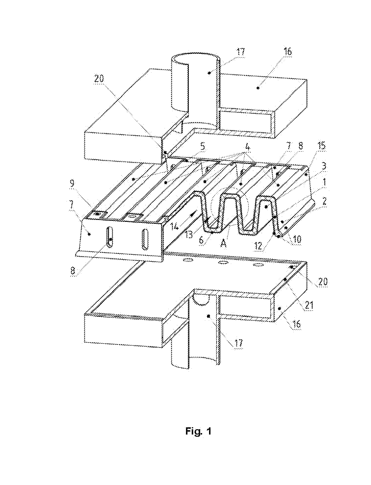
[0064]the planar cell is shown in FIG. 5.

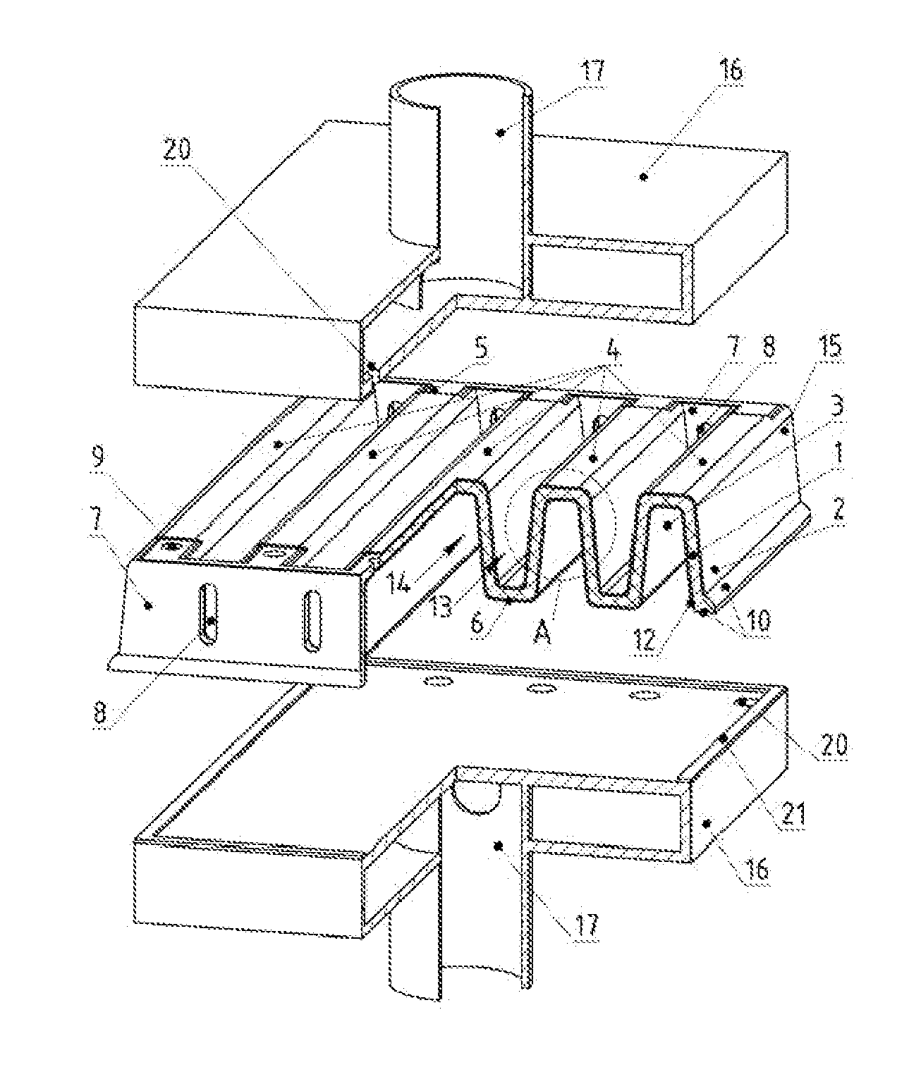
[0065]In this case, the modified planar cell with electrochemical part 15, for example, with supporting solid electrolyte 1 and electrodes, cathode 2 and anode 3, has two rows of apertures: one row, for example, the upper one, includes apertures 9 in the front and rear walls 7 made from solid electrolyte or structural ceramic for fuel supply into -shaped channels. The other row, for example, the lower one, contains apertures 8 with a larger section for air supply into -shaped SOFC channels and for hypoxic mixture removal from the planar cell. The lower and upper rows of apertures are located on the front lateral wall. If the battery is manufactured from a series set of cells along the vertical axis, it is reasonable to use the structure of the planar cell electrochemical part as end cells. The upper gas and current manifold 16 is manufactured from electron conducting material, for example, high-chromium steel, e.g. Crofer 22 APU. It is connec...

first embodiment

[0066]For a series electrical connection of the planar cells, as well as for higher voltage generation, the planar cells (variants) can be assembled into the battery (the first variant) along the vertical axis. In this case, each subsequent cell is rotated by 180, FIG. 6 (as an example the figure shows the planar cell).

[0067]The battery consists of several cells 15 (as an example only two cells are shown) and has input and output gas manifolds 16 with the metallic box-like gas supply ducts 17 for fuel supply and reaction products removal correspondingly. The metallic box-like gas supply ducts 17 simultaneously serve as current collectors (clamps) of the battery. The metallic box-like gas supply ducts 17 inside box-like gas manifolds 16 have an aperture for uniform distribution of reagent gas flows in the planar cell by apertures 9. These metallic box-like gas supply ducts 17 are connected mechanically and electrically with a gas distributing plate with apertures 20 and gas manifold ...

second embodiment

[0069]FIG. 7 shows the battery.

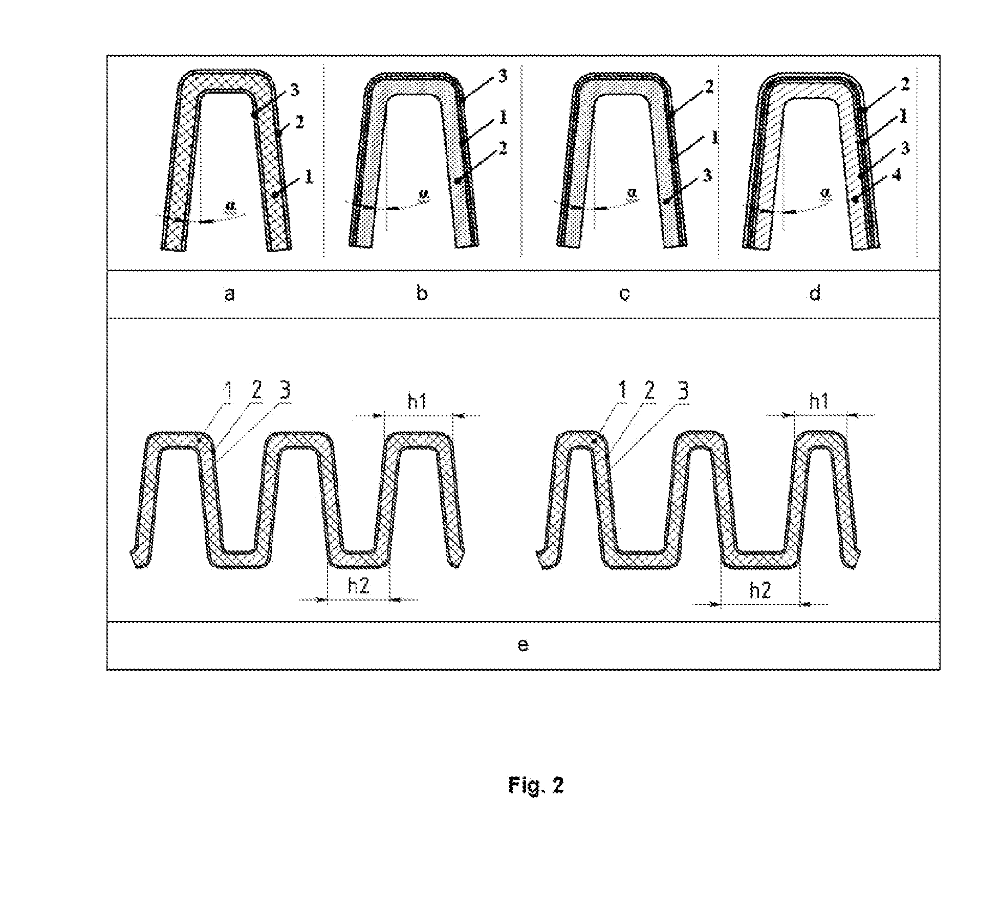
[0070]Structurally, the electrochemical and ceramic part, the fuel distribution, the fuel and oxidant supply assemblies, and the reagent removal assemblies are provided in a manner similar to those of the single cell. However, the corrugated plate 4 from the solid electrolyte (see prototype, FIG. 3 and FIG. 1, 4, 5) has several pairs of electrodes rather than two electrodes, one as a cathode at the top and a second as an anode at the bottom. Thus, one ceramic blank may represent one SOFC comprising five -shaped fuel channels and four -shaped air channels, or such ceramic blank may represent a battery of two cells, if the anode of the left cell (2.5 of -shaped channels) is electrically connected with the cathode of the right cell (2.5 of -shaped channels) and the third -shaped fuel channel. The battery is formed of five cells, if each -shaped fuel channel is a cell, and their series electrical connection is an anode of the previous cell with a cathode o...


PUM

PropertyMeasurementUnit
Angleaaaaaaaaaa
Angleaaaaaaaaaa
Lengthaaaaaaaaaa

Abstract

The invention relates to a modified planar cell with a solid-oxide solid electrolyte, a gas-diffuse anode, a cathode, a metal or oxide current path and a current-gas supply. The supporting solid electrolyte of the cell is in the form of a corrugated plate consisting of corrugations. In cross-section, the corrugations of the plate constitute an isosceles, identical-height trapezium, without a larger lower base with holes. The holes are formed on one side in the upper part of each corrugation, for supplying one of the reagents, e.g. fuel in case of a fuel cell. The corrugations are connected to one another at their base in order to form gas space channels of the cell. The gas space channels are in the form of inverted isosceles trapezia without a larger upper base and the angle α at their smaller base is 0.1 to 89.9°. The corrugated plate is connected to two opposing walls, a front wall and a rear wall. The latter is arranged perpendicular to the corrugations of the plate and thus of equal height, and is furnished with holes. The holes in one wall are used for introducing a second reagent, e.g. air in the case of a fuel cell, into each channel of the electrode environment in the form of inverted isosceles trapezia without the larger upper base and the holes of the other opposing wall for discharging the hypoxic mixture. On one side of the gas space channels constituting, in cross-section, an isosceles trapezium without larger lower base, the corrugated plate of the supporting solid electrode is coated with an electrode, e.g. a nickel-cermet anode in the case of a fuel cell. On the side of the gas space channels of the electrode environment, which are shaped in the form of inverted isosceles trapezia without the larger upper base, the plate is coated with a second, counter-electrode, e.g. a cathode based on strontium-lanthanum-manganite. The metallic box-like gas supply duct ensures the supply of reagents and the discharge of reaction products with a series of holes. The width and the length of the gas supply duct coincide with those of the cell. These holes correspond to the holes in the upper parts of the corrugations of the cell that constitute, in cross-section, an isosceles trapezium without a larger lower base and are connected in a gas-tight manner to the periphery of the holes. A gas-tight space is formed in the planar cell for the reagent introduced via a tube, for the uniform distribution thereof via the gas space channels and for the exit of the exhaust gases through a similar discharge gas manifold. The discharge gas manifold is rotated by 180° relative to the vertical axis and is connected in a gas-tight manner to the ceramic part at the periphery. The flat surfaces of the gas manifolds furnished with holes are connected to the electrodes. They are simultaneously used as current collectors and the tubes are used as current terminals of the planar cell.

Description

CROSS-REFERENCE TO RELATED APPLICATION[0001]This application claims the benefit of the priority filing date in PCT / IB2012 / 002774 filed on Dec. 20, 2012, and referenced in WIPO Publication No. WO / 2013 / 093607. The earliest priority date claimed is Dec. 22, 2011.FEDERALLY SPONSORED RESEARCH[0002]NoneSEQUENCE LISTING OR PROGRAM[0003]NoneBACKGROUND[0004]1. Field of the Invention[0005]The invention relates to high-temperature electrochemical devices (ECD) based on solid electrolytes, for example, to electrochemical generators (fuel cells), electrolyzers, converters, pumps and other devices. Specifically, the invention relates to a planar cell design of such devices, to the design of any ECD battery with gas manifolds for at least one reagents, e.g. fuel, and to a manufacturing method for the planar cell and battery (stack) of such design.[0006]2. Background Information[0007]More sophisticated ECDs are known, namely, solid oxide fuel cells (SOFC) for direct conversion of fuel chemical ener...

Claims


Application Information

Patent Timeline
IPC IPC(8): H01M8/12H01M4/86
CPCH01M8/122H01M4/8605H01M2008/1293H01M2300/0077H01M8/1253Y02E60/525Y02E60/521H01M8/1226H01M8/2425H01M8/1246H01M8/0254H01M8/2485H01M8/2432H01M8/2457Y02E60/50Y02P70/50
Inventor LIPILIN, ALEKSANDR S.LIPLINA, VIKTORIA S
Owner LIPILIN ALEKSANDR S
Why Eureka
Try Eureka