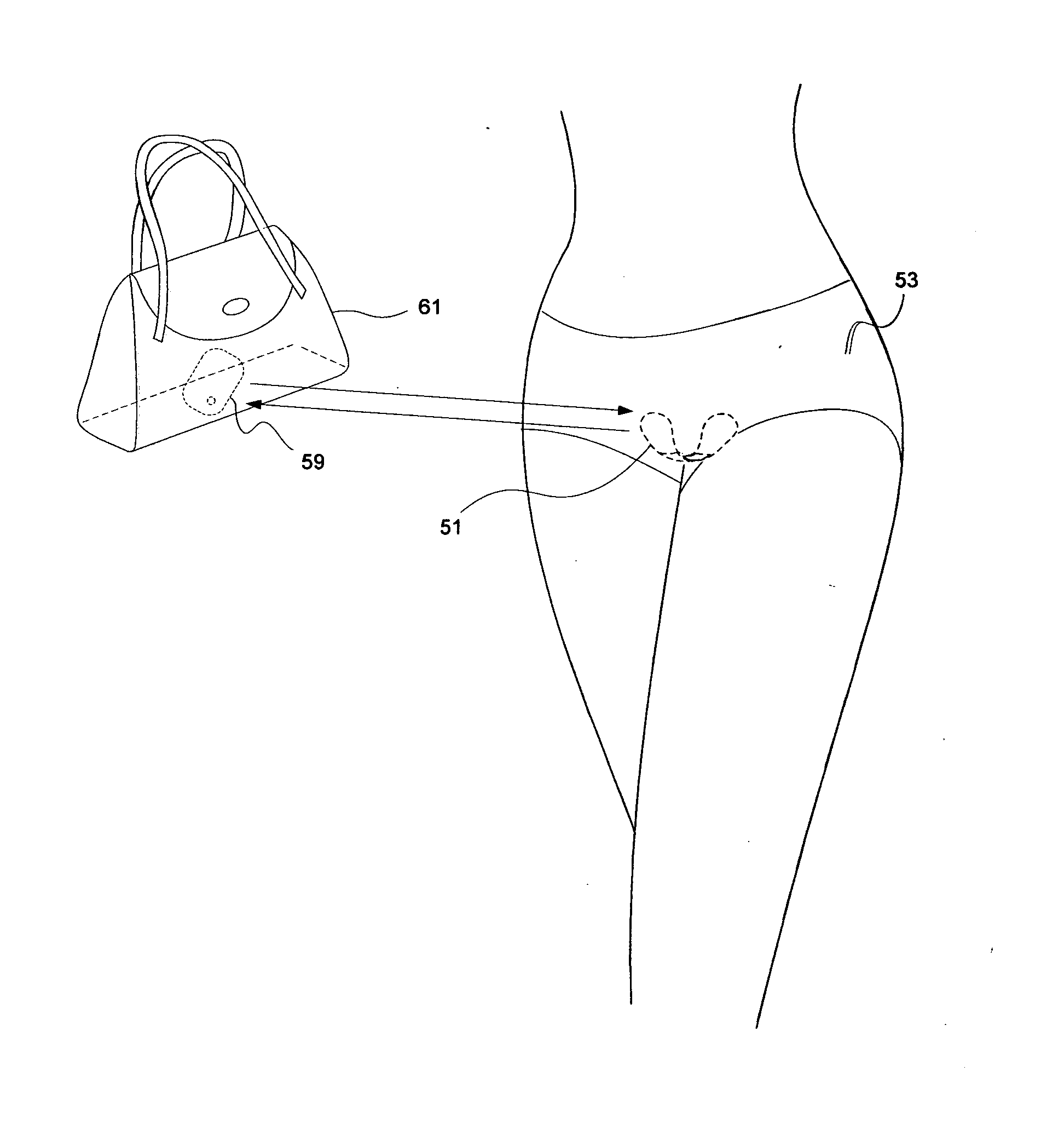
Real-time blood detection system
a real-time detection and blood technology, applied in medical science, surgery, vaccination/ovulation diagnostics, etc., can solve the problems that none of these innovations can be considered full proof means of preventing blood leakage, and women are faced with having to wear feminine hygiene products well, so as to achieve no sensation and easy installation
- Summary
- Abstract
- Description
- Claims
- Application Information
AI Technical Summary
Benefits of technology
Problems solved by technology
Method used
Image
Examples
example implementations
and Link Budget
[0130]Reference is made to channel propagation models for body surface to body surface non-line-of-sight (NLOS) propagation. These models have been developed by the IEEE Working Group for Wireless Personal Area Networks (WPANs) to address the needs of Body Area Networks development.
[0131]The document “IEEE P802.15-08-0780-09-0006” summarizes the activities and recommendations of the channel modeling subgroup of IEEE802.15.6 (Body Area Network). This guidance is developed for Body Area Networks relating to medical and non-medical devices that could be placed inside or on the surface of human body. The results of theoretical studies and measurement campaigns are provided therein. Path loss and fading models resulting from this work are summarized in the table below for candidate transmission frequency bands comprising those that are unlicensed. Models are provided for the second harmonic frequencies as well. Channel calculations based on the models are used herein for t...
embodiment implementation
PREFERRED EMBODIMENT IMPLEMENTATION
First Example
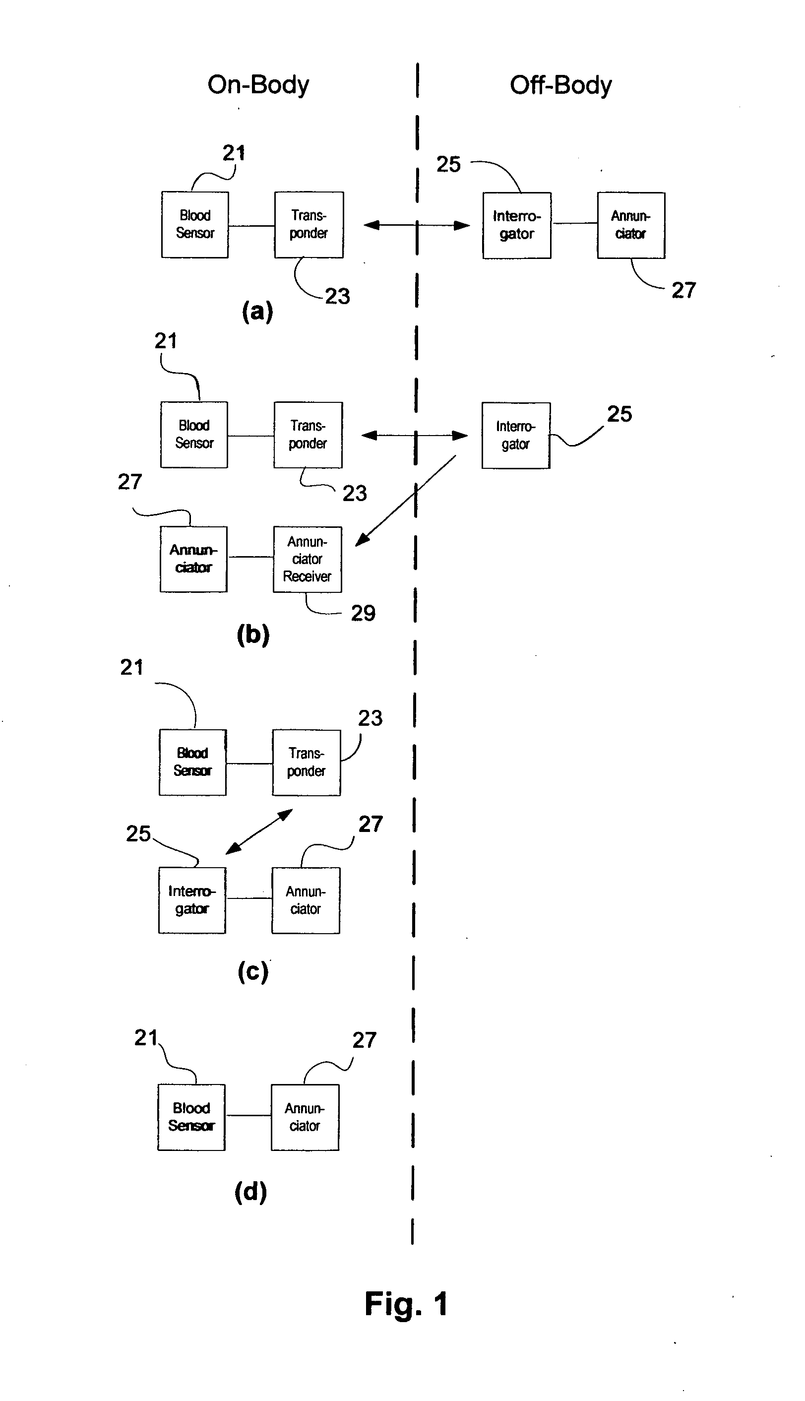
[0141]The transponder is the EM4325 device operated in battery assisted passive (BAP) mode thereby achieving a sensitivity of −31 dBm in the 900 MHz ISM band. The power source is a printed paper battery exhibiting a capacity of 4.5 mAhr per square centimeter. The blood sensor is used to create a change from low impedance to high impedance between device pins 2 and 3, thereby signaling an alarm condition. The interrogator is a simplified RFID reader for this device comprising a UHF front end and microcontroller that implements a simplified read protocol. Specifically, a transmitter chip would be combined with a separate receiver chip in order to implement the full duplex TOTAL (Tag Only Talks After Listening) protocol of the ISO 18000 (RFID Air Interface Standards) specification. A number of commercially-available, inexpensive parts exist for the 900 MHz ISM band.
[0142]In this reduction to practice, the interrogator periodically sends a...
second example
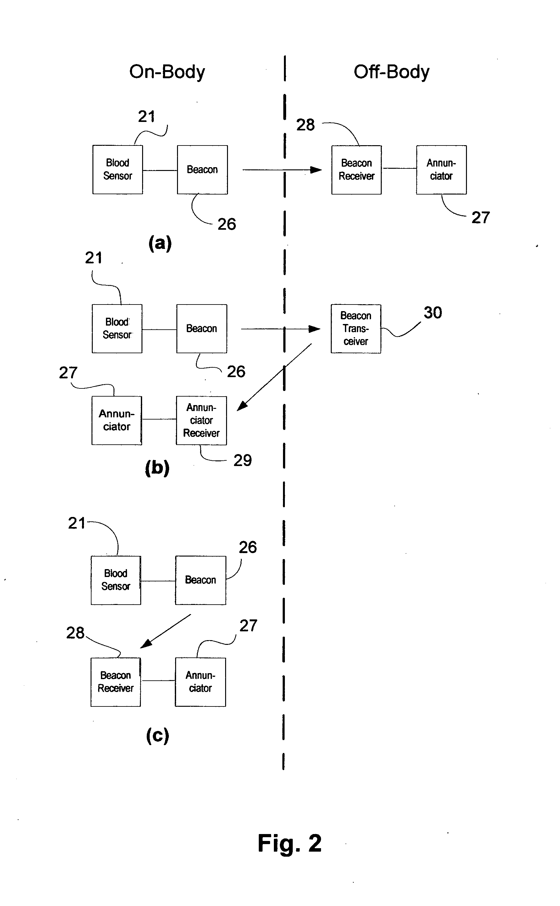
[0145]An example beacon system comprises use of a low cost, low current transmitter such as the Si4012. The transmitter chip would require minimal circuitry for interface to impedimetric, amperometric, or potentiometric sensors. A good candidate beacon receiver is the Si4362 with a sensitivity of −126 dBm.
Sensor Interface with Communication Devices
[0146]For amperometric sensors, typically a transimpedance amplifier is used to convert the current signal to a voltage signal. For impedimetric sensors, a factor of ten increase in impedance swing is achievable with an impedance multiplier circuit as is well known in the prior art. The impedance variation can be transduced to a voltage signal using a Wheatstone bridge or voltage divider with instrumentation amplifier.
[0147]Alert-type sensor outputs which are indicative of blood presence will be signals that broach a threshold. If they are current or impedance signals, they can be transduced to voltage signals for direct analog or digital ...
PUM
 Abstract
Description
Claims
Application Information
 - R&D
- Intellectual Property
- Life Sciences
- Materials
- Tech Scout
- Unparalleled Data Quality
- Higher Quality Content
- 60% Fewer Hallucinations
Browse by: Latest US Patents, China's latest patents, Technical Efficacy Thesaurus, Application Domain, Technology Topic, Popular Technical Reports.
© 2025 PatSnap. All rights reserved.Legal|Privacy policy|Modern Slavery Act Transparency Statement|Sitemap|About US| Contact US: help@patsnap.com


