Method for non-intrusive measurement of low water content in oil

a technology of low water content and measurement method, which is applied in the direction of measurement devices, material analysis through optical means, instruments, etc., can solve the problems of not being able to measure water concentration locally, methods are not well-adapted to the different design parameters, and it is more difficult to quantify or even identify water. , to achieve the effect of reducing the diameter of pulsed laser beam

Active Publication Date: 2015-06-18
SAUDI ARABIAN OIL CO
View PDF5 Cites 16 Cited by
  • Summary
  • Abstract
  • Description
  • Claims
  • Application Information

AI Technical Summary

Benefits of technology

[0022]In certain embodiments of the present invention, the apparatus further includes a barrier defining a fixed opening, the fixed opening located between the cuvette and the laser source, wherein the fixed opening is configured to reduce a diameter of the pulsed laser beam. In certain embodiments of the present invention, the average diameter of the water droplets is in a range between 30 μm and 70 μm. In certain embodiments of the present invention, the pulsed laser beam has a wavelength of 266 nm. In certain embodiments of the present invention, the fluorescence spectrum is in a range between 280 nm and 450 nm. In certain embodiments of the present invention, the spectrograph is located between the collecting lens and the intensified charge coupled device, and wherein the intensified charge coupled device is synchronized with the pulsed laser beam. In certain embodiments of the present invention, the pulsed laser beam pulses for a temporal span of 6 ns / pulse at an energy of 20 mJ / pulse. In certain embodiments of the present invention, the slit is 0.5 mm wide. In certain embodiments of the present invention, the slit is 4 mm from an edge of the cuvette.

Problems solved by technology

The contamination of jet fuel by condensation water is known to be a serious safety concern in the aviation industry and was found to be the cause of several helicopter crashes in hot and humid tropical countries.
Common analytical methods of testing for contaminants include using infrared absorption, ultra violet (UV) absorption, and nuclear magnetic resonance, but each of these contain drawbacks.
A more difficult contaminant to quantify or even to identify is water.
These methods are not well-adapted for the different design parameters facing water-in-oil measurement for water concentrations in the range from 0.01% up to a few percent by volume, because water does not fluoresce, the prominent fluorescence signal from the oil will not be appreciably affected by the presence of only minute amounts of water.
The inability to accurately measure low concentrations of water in oil means there is no good way of measuring water concentration locally inside a water-in-oil emulsion flow domain.
Consequently, there is almost no experimental data on water concentration gradients inside flowing emulsion layers available to the scientific community.
In addition, none of the methods known in the prior art describe a direct correlation between laser-induced fluorescence intensity measurements of oil in a water-in-oil mixture and the water content in the mixture.
This and other techniques involving sampling, dilution, and several successive manipulations in a laboratory environment make them impractical for real-time process monitoring applications as needed in crude oil production facilities as well as in oil refineries and petrochemical plants, because they are intrusive to flowing fluids.
These methods are also ill suited to measuring local water content in a tank or other holding device.

Method used


Image

  • Method for non-intrusive measurement of low water content in oil
  • Method for non-intrusive measurement of low water content in oil
  • Method for non-intrusive measurement of low water content in oil

Examples


example 1

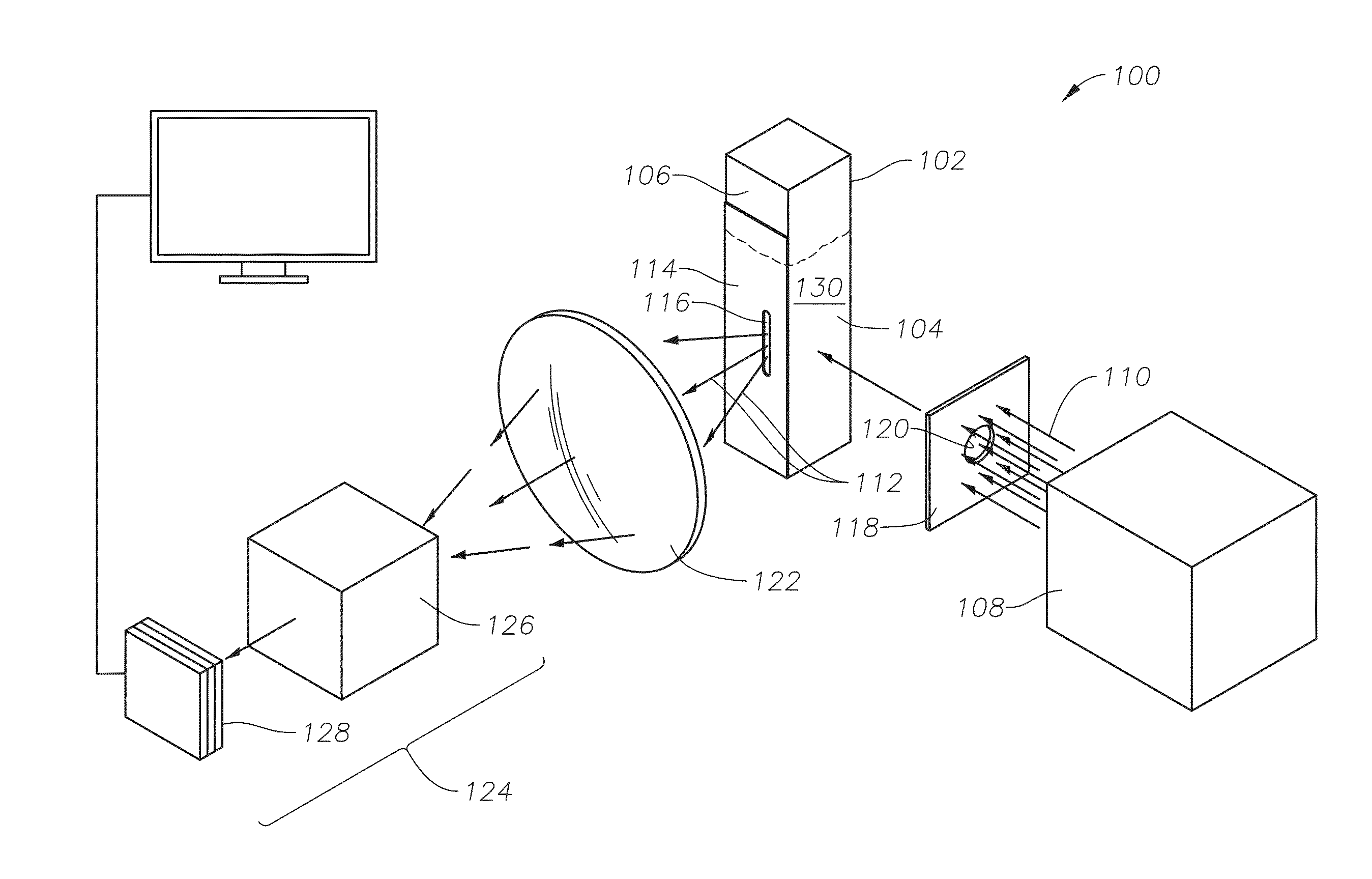
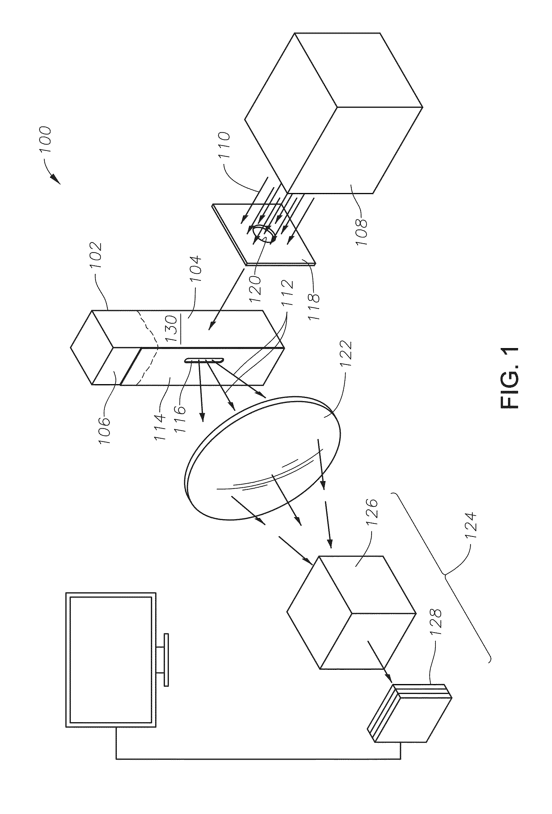
[0055]In Example 1, the oil-containing fluid was jet fuel grade kerosene. The sample of low water content fluid was created by collecting a sample of the jet fuel grade kerosene in a 1000 mL beaker and adding an amount of water. A pipette was used to add a known amount of distilled water to the jet fuel grade kerosene to create a low water content fluid having 7000 ppm water (corresponding to an amount of water of 1% by volume). The amount of water in the sample was controlled by using pipettes to add distilled water to the kerosene sample. A high-speed handheld blender was used to blend the sample by setting an angular speed of the mixing rotor of the blender to 13,500 rpm and allowing the sample to mix for a duration of 2 minutes. At the end of the blending step, the sample contained water droplets with a size distribution of 30 μm to 70 μm in diameter, with an average diameter of 50 μm. After the sample was blended, an eyedropper was used to take between 3 mL and 4 mL from the ap...

example 2

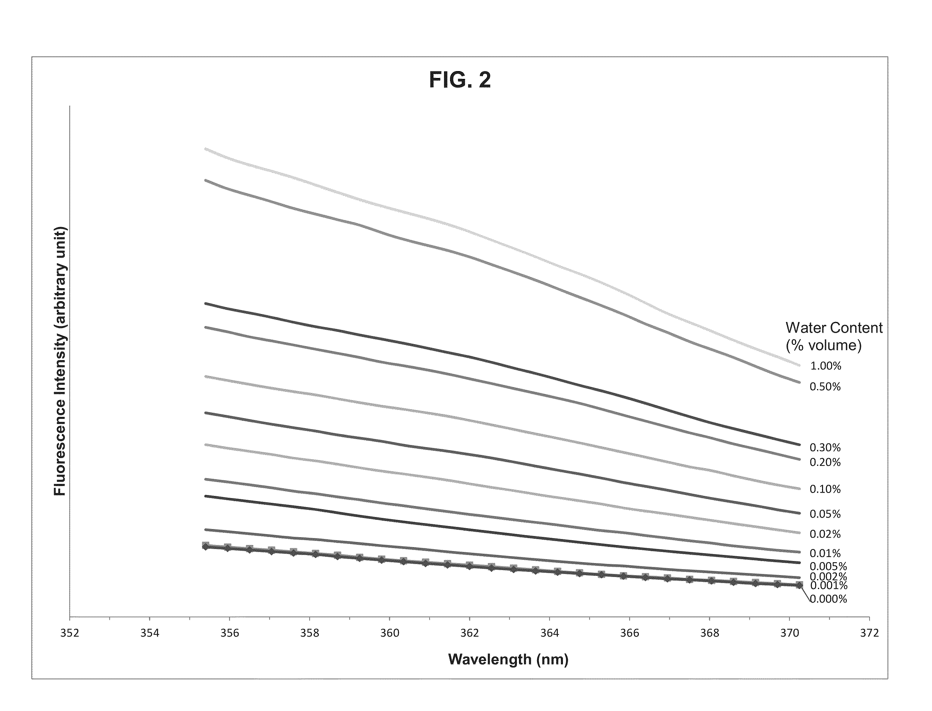
[0056]In Example 2, the fluorescence measurement process of Example 1 was repeated under identical conditions for samples having amounts of water of 7 ppm, 14 ppm, 35 ppm, 70 ppm, 140 ppm, 210 ppm, 350 ppm, 700 ppm, 1400 ppm, 3500 ppm, and 7000 ppm (corresponding to an amount of water in the low water content fluid of 0.001%, 0.002%, 0.005%, 0.01%, 0.02%, 0.05%, 0.1%, 0.2%, 0.5%, and 1% by volume, respectively). A volumetric water content between 0.001% and 1.00% corresponds to a water content in the sample between 7 ppm and 7000 ppm. For each sample, the fluorescence intensity of the sample was measured. FIG. 2 is a plot of the fluorescence intensity of each of the samples over a range of the fluorescence spectrum having wavelengths between 355 nm and 375 nm. The fluorescence intensity was integrated over the range of the fluorescence spectrum shown in FIG. 2 and plotted in three ranges corresponding to three orders of water content in the samples. The first range included samples ...


PUM

PropertyMeasurementUnit
diameteraaaaaaaaaa
diameteraaaaaaaaaa
wavelengthaaaaaaaaaa

Abstract

The present invention relates to a method and apparatus for determining trace amounts of water in oil, including the steps of obtaining a blended sample of a low water content fluid including an amount of water and an amount of oil, transferring a portion of the blended sample to a cuvette to create a measurement sample, covering a viewing surface of the cuvette with an opaque sheet with a slit, providing a barrier with a fixed opening between a laser source and a laser-receptive surface of the cuvette, transmitting a pulsed laser beam from the laser source into the cuvette; inducing fluorescence in the measurement sample, focusing the fluorescence through a collecting lens and transmitting the fluorescence to a spectrometer, and measuring the fluorescence with the spectrometer by dispersing the fluorescence with a spectrograph and intensifying the fluorescence with an intensified charge coupled device.

Description

FIELD OF THE INVENTION[0001]The invention relates to a method for determining water content in petroleum fluids. Specifically, the invention relates to a non-intrusive method for rapidly determining the water content in petroleum fluids based on spectroscopic measurements of laser-induced fluorescence emitted from a water-oil mixture.BACKGROUND OF THE INVENTION[0002]Analytical testing for contaminants in a petroleum fluid is an important step in many industrial processes. Contaminants can be in the form of small amounts of other types of fuels which have remained, for example, in multi-purpose pipelines or refined oil storage tanks. Contaminants can be in the form of small amounts of the same fuel but having different sulfur contents, which commonly happens in diesel fuel distribution operations and storage. The contaminants can also be in the form of weathered fuels mixed with fresh ones or in the form of some chemicals that cannot readily be identified.[0003]Water as a contaminant...

Claims


Application Information

Patent Timeline
Patent Type & Authority Applications(United States)
IPC IPC(8): G01N33/28G01N21/03G01N21/64
CPCG01N33/2847G01N21/6402G01N2021/6417G01N2201/06113G01N21/0303G01N21/64
Inventor HEGAZI, EZZAT M.AKHRAS, ABDUL RAHMAN ZAFER
Owner SAUDI ARABIAN OIL CO
Why Eureka
Try Eureka