Reduced trace metals contamination ion source for an ion implantation system

a technology of ion implantation system and trace metals, which is applied in the field of reducing trace metal contamination ion source, can solve the problems of deleterious introduction of impurities, increase the complexity of devices, and shorten the lifetime of materials, and achieve the effect of reducing trace metal contamination

Active Publication Date: 2015-06-25
AXCELIS TECHNOLOGIES
View PDF10 Cites 48 Cited by
  • Summary
  • Abstract
  • Description
  • Claims
  • Application Information

AI Technical Summary

Benefits of technology

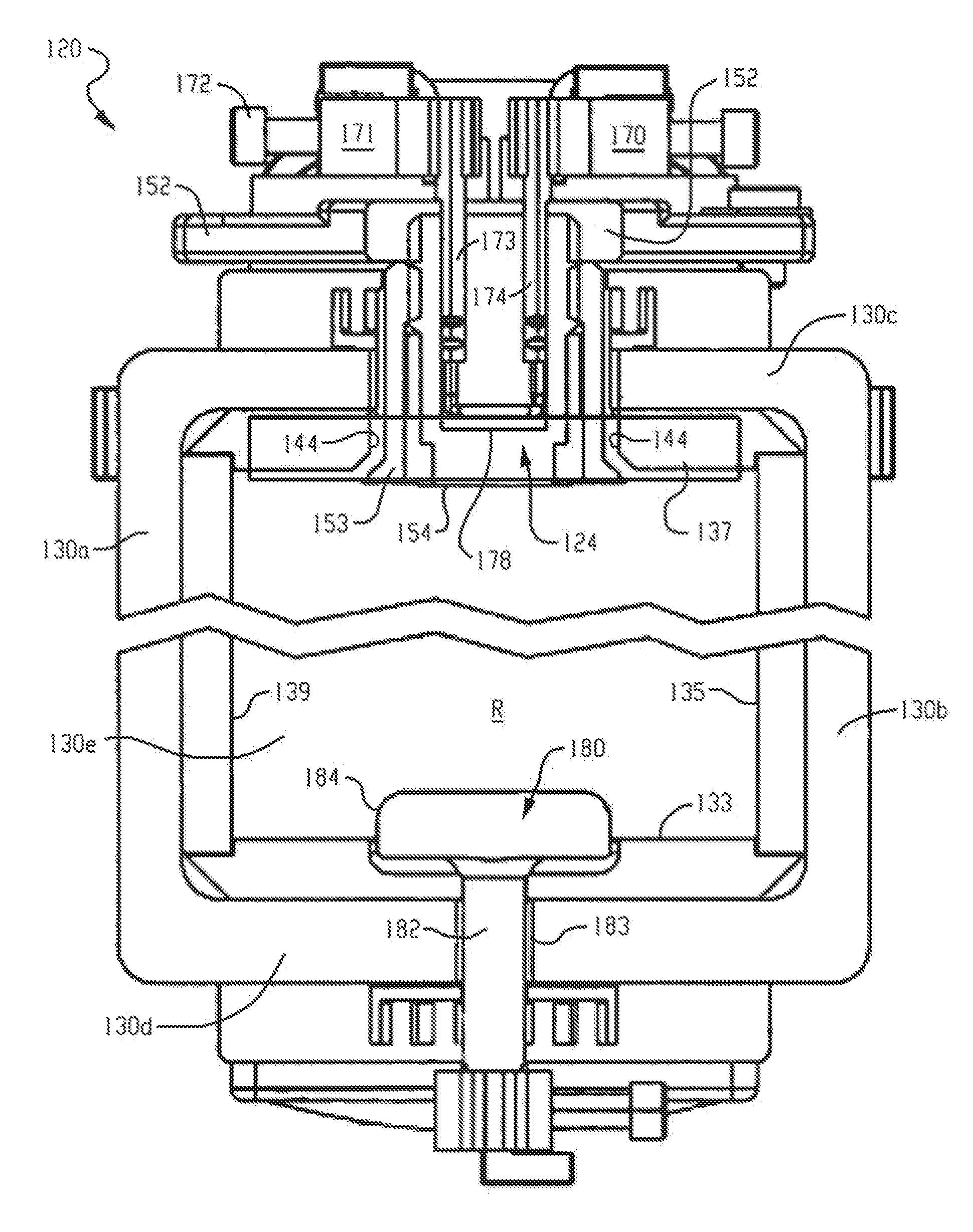
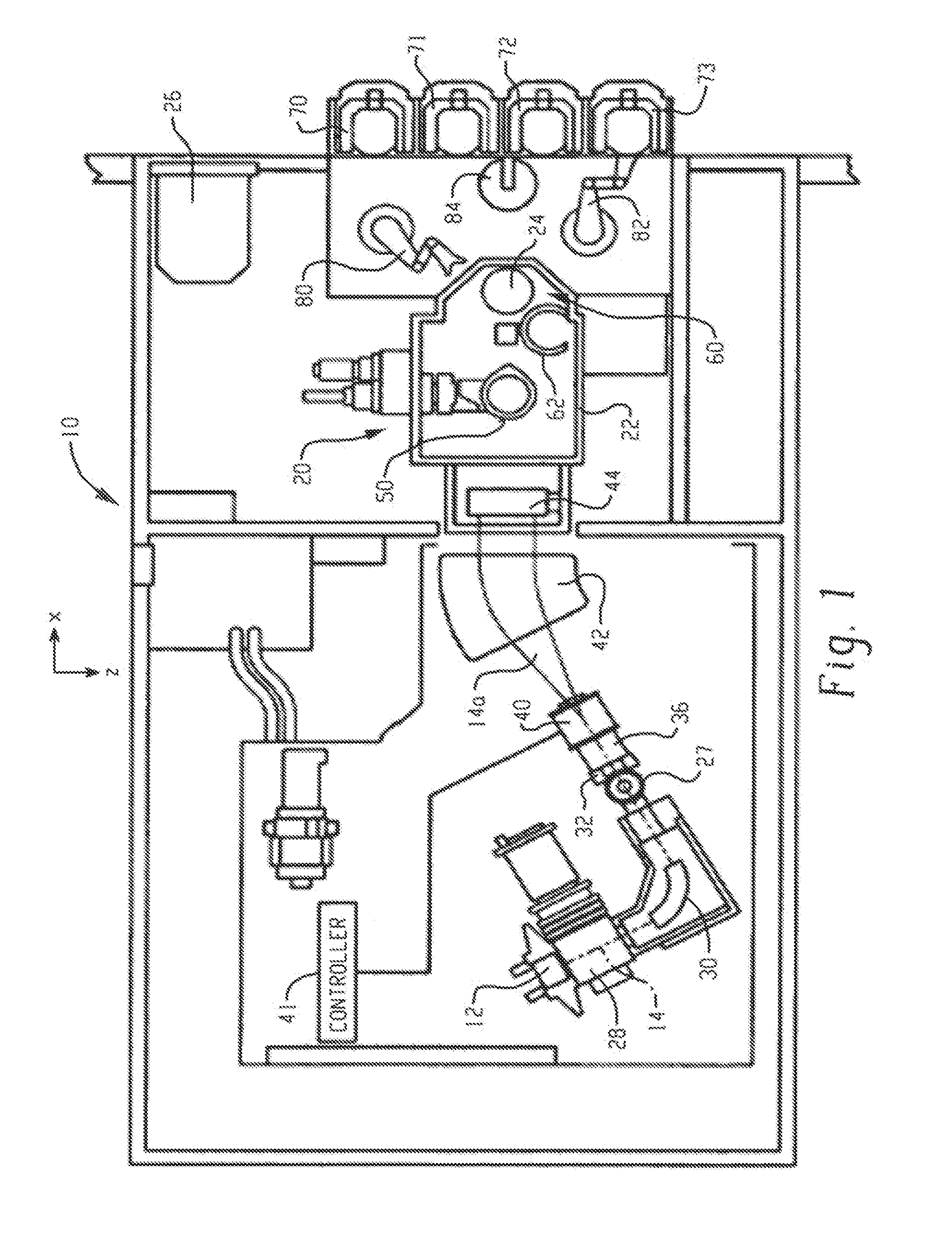
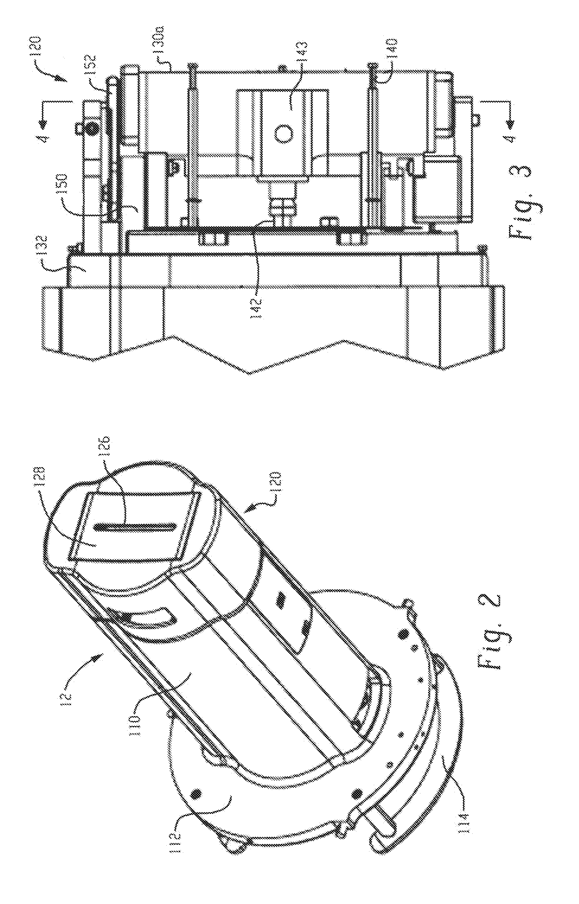
[0013]Disclosed herein is a reduced trace metal contamination ion source for use in ion implantation systems. In one embodiment, an ion source chamber for an ion implantation system, the ion source chamber comprises a housing that at least partially bounds an ionization region through which high energy electrons move from a cathode to ionize gas molecules injected into an interior of the housing; a liner section defining one or more interior walls of the housing interior, wherein each liner section includes a interiorly facing surface expose

Problems solved by technology

In addition, the continuing trend toward higher device complexity requires careful control over the uniformity of implantation beams being scanned across the workpiece.
Corrosion of these materials can occur when ionizing fluorine-based compounds such as BF3, GeF4, SiF4, B2F4 and/or oxygen-based compounds such as CO and CO2, which can dramatically shorten the lifetimes of these materials as well as deleteriously introduce impurities during ion implantation.
These materials are corrosive by themselves and the presence of these corrosive materials within the chamber can further propagate a halogen cycle where the deposition of these materials within the ion source chamber may occur, which significantly shortens operating lifetimes of these components.
When ionizing oxygen-based compounds such as CO and CO2, the fo

Method used


Image

  • Reduced trace metals contamination ion source for an ion implantation system
  • Reduced trace metals contamination ion source for an ion implantation system
  • Reduced trace metals contamination ion source for an ion implantation system

Examples


examples

[0050]In this example, surface metal contamination of a BF2 14 keV high dose implants was measured in an Optima HDx ion implantation system commercially available from Axcelis Technologies, Inc. having a tungsten repeller and the same ion implantation system wherein the tungsten repeller was replaced with a silicon carbide repeller of the same dimensions. The SiC was Hexoloy SG. Bare wafers with 200 angstroms of thermally grown oxide were implanted with a dose of 5×10¹⁵ ions / cm2 at a beam current of 14 mA. The BF2 ions were generated from BF3. All other test parameters were identical for both the tungsten and silicon carbide repellers. Prior to each sample run, the ion source chamber was exposed to a 30 minute high power argon beam. Surface contamination was measured using vapor phase decomposition inductively coupled plasma mass spectroscopy (VPD ICP-MS). The results are shown in Table 1 below.

TABLE 1REPELLERCOMPOSITIONPure TungstenSilicon CarbideSURFACE14.55.8CONTAMINATION(×1010 a...


PUM


Abstract

An ion source chamber for ion implantation system includes a housing that at least partially bounds an ionization region through which high energy electrons move from a cathode to ionize gas molecules injected into an interior of the housing; a liner section defining one or more interior walls of the housing interior, wherein each liner section includes a interiorly facing surface exposed to the ionization region during operation the ion implantation system; a cathode shield disposed about the cathode; a repeller spaced apart from the cathode; a plate including a source aperture for discharging ions from the ion source chamber; wherein at least one of the repeller, the liner section, the cathode shield; the plate, or an insert in the plate defining the source aperture comprise silicon carbide, wherein the silicon carbide is a non-stoichiometric sintered material having excess carbon.

Description

BACKGROUND[0001]The present disclosure generally relates to ion implantation systems, and more particularly, to a reduced trace metal contamination ion source of the type typically used in ion implantation systems, which exhibits improved corrosion resistance within the arc chamber of the ion source.[0002]Ion implantation systems or ion implanters are widely used to dope semiconductors with impurities in integrated circuit manufacturing, as well as in the manufacture of flat panel displays. In such systems, an ion source ionizes a desired dopant element, which is extracted from the source in the form of an ion beam of desired energy. The ion beam is then directed at the surface of the workpiece, such as a semiconductor wafer, in order to implant the workpiece with the dopant element. The ions of the beam penetrate the surface of the workpiece to form a region of desired conductivity, such as in the fabrication of transistor devices in the wafer. The implantation process is typically...

Claims


Application Information

Patent Timeline
IPC IPC(8): H01J37/08
CPCH01J37/08H01J2237/0213H01J2237/082H01J37/3171H01J2237/0268H01J2237/31705
Inventor COLVIN, NEILHSIEH, TSEH-JEN
Owner AXCELIS TECHNOLOGIES
Why Eureka
Try Eureka