Biodegradable composite wire for medical devices

a biodegradable, composite wire technology, applied in the direction of magnet bodies, prostheses, magnetic materials, etc., can solve the problems of increasing mechanical fatigue, limiting re-intervention, inhibiting further natural positive remodeling of the vessel, etc., to reduce the potential for pitting corrosion and enhance strength

Inactive Publication Date: 2015-07-02
FORT WAYNE METALS RES PROD CORP
View PDF3 Cites 31 Cited by
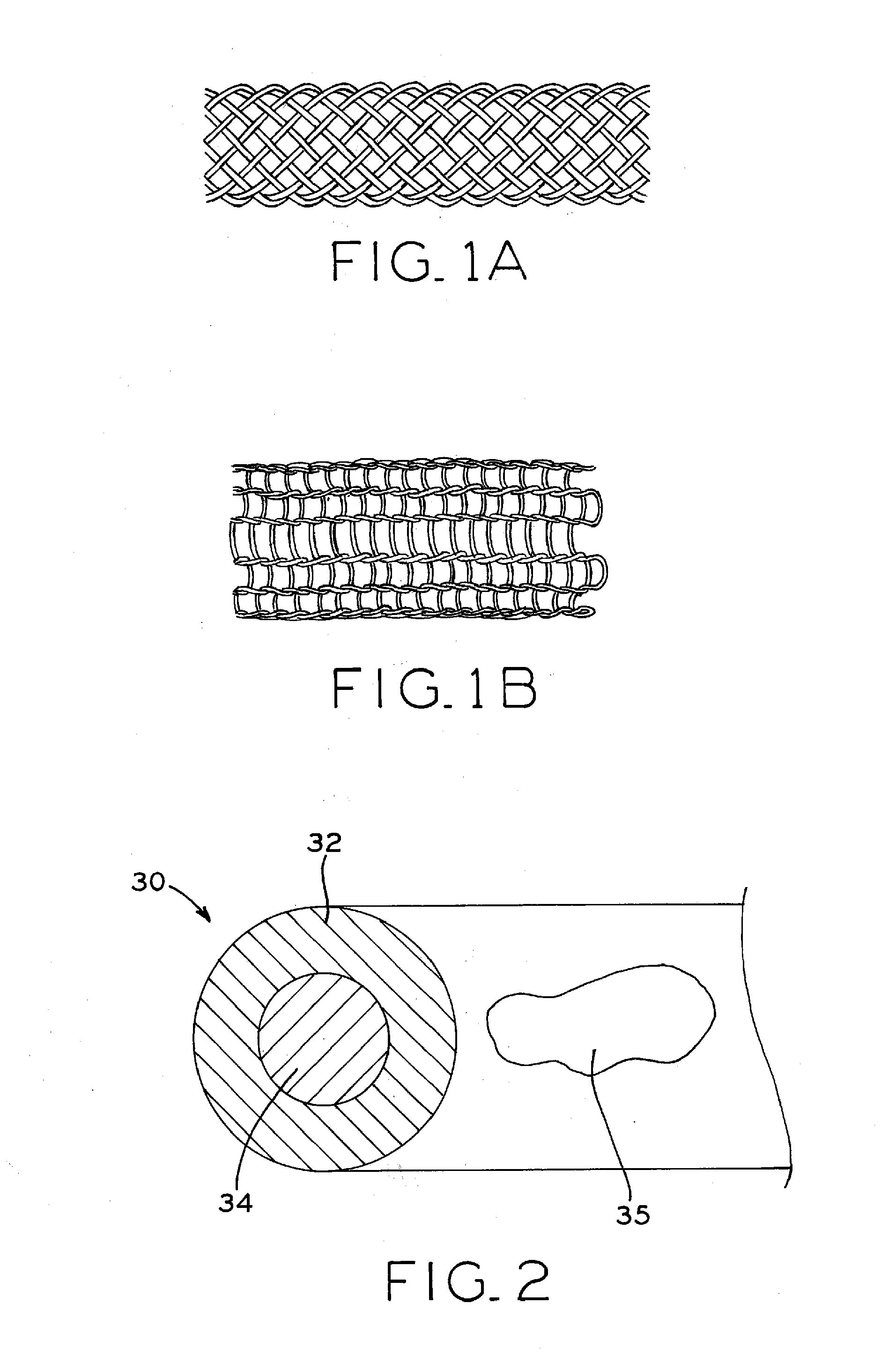
  • Summary
  • Abstract
  • Description
  • Claims
  • Application Information

AI Technical Summary

Benefits of technology

[0013]The present disclosure provides a bioabsorbable wire material including manganese (Mn) and iron (Fe), in which one or more additional constituent materials (X) are added to control corrosion in an in vivo environment and, in particular, to prevent and/or substantially reduce the potential for pitting corrosion. For example, the (X) element in the Fe—Mn—X system may include nitrogen (N), molybdenum (Mo) or chromium (Cr), or a combination of these. This

Problems solved by technology

In contrast to most thoracoabdominal implantation sites (such as in coronary arteries), upper and lower limb anatomy is typically subjected to greater range of motion, thereby potentially increasing mechanical fatigue.
After such remodeling is complete, the stent may no longer be needed for mechanical support and could potentially inhibit further natural positive remodeling of the vessel or limit re-intervention, for example.
However, removal of an implanted stent may be difficult.
While such materials are resorbable, they may have low mechanical strength and resilience, and/or may confer inadequate control over the rate of bioabsorption (i.e., by biodegrading too slowly or quickly in vivo).
However, iron-manganese alloys may have insufficient

Method used


Image

  • Biodegradable composite wire for medical devices
  • Biodegradable composite wire for medical devices
  • Biodegradable composite wire for medical devices

Examples


example 1

Monolithic Fe—Mn—X Alloy Wire Materials

[0129]In this Example, exemplary monolithic Fe—Mn wires alloyed with Cr, Mo, N or a combination thereof were produced, characterized and tested.

[0130]A Pitting Resistance Equivalent Number (PREN) can be used to compare the pitting corrosion resistance of various types of materials, based on their chemical compositions. In the present Example, PREN is calculated as:

PREN=Cr+3.3(Mo+0.5W)+16N,

in which all factors are expressed as a wt. % quantity.

[0131]Table 1-1 summarizes the PREN for wires made in accordance with the present disclosure. As shown, nine wire samples were produced, with groups of three samples having varying levels of Cr, Mo and N used as alloying elements. Each group of three samples alloyed varying wt. % amounts of a given alloying element as shown.

TABLE 1-1Pitting Resistance Equivalent Number (PREN) for various Fe—MnAlloy Wires Made in Accordance with the Present DisclosureTrialFeMnCrMoNNo.(wt. %)(wt. %)(wt. %)(wt. %)(wt. %)PRENb...

example 2

Monolithic Fe—Mn—X Alloy Wire Materials

[0133]In this Example, exemplary monolithic wires were produced, tested and characterized.

[0134]1. Production of Fe—Mn—X Monolithic Wires

[0135]Ingots were melted and cast into a 12.7 mm diameter by 150 mm length pre-form. Ingots with target chemistries in accordance with Table 1-1 were created by arc melting from primary metals of 99.95 wt. % minimum purity. These ingots were cold-formed into wire through conventional cold-working techniques including swaging and wire drawing combined with iterative annealing in order to restore ductility between respective cold-forming steps. All wires received a final recrystallization anneal treatment at a diameter of 0.64 mm prior to cold wire drawing to a finish diameter of 0.102 mm for testing and characterization.

[0136]2. Characterization of Fe—Mn—X Monolithic Wires

[0137]The rate of degradation of bioabsorbable materials can be measured in a laboratory using a simulated bodily environment, e.g. saline or...

example 3

Additional Candidate Materials for DFT Constructions

[0143]In this Example, exemplary bimetal composite wires and high strength iron monolith wires were produced, tested and characterized. In addition, three benchmark alloy wires were produced, tested and characterized for comparison to the exemplary wires.

[0144]1. Production of Bimetal Composite and Monolithic Wires

[0145]For Wire #1-3 in Tables 3-1 and 3-4 below, a pure Fe rod of dimension F mm outside diameter (OD) was processed as monolithic (solid) wire.

[0146]Similarly, for Wire #7-9 in Tables 3-3 and 3-4 below, 316L stainless steel, MP35N and Nitinol alloy wire respectively, of dimension H mm outside diameter (OD) were processed as monolithic wire.

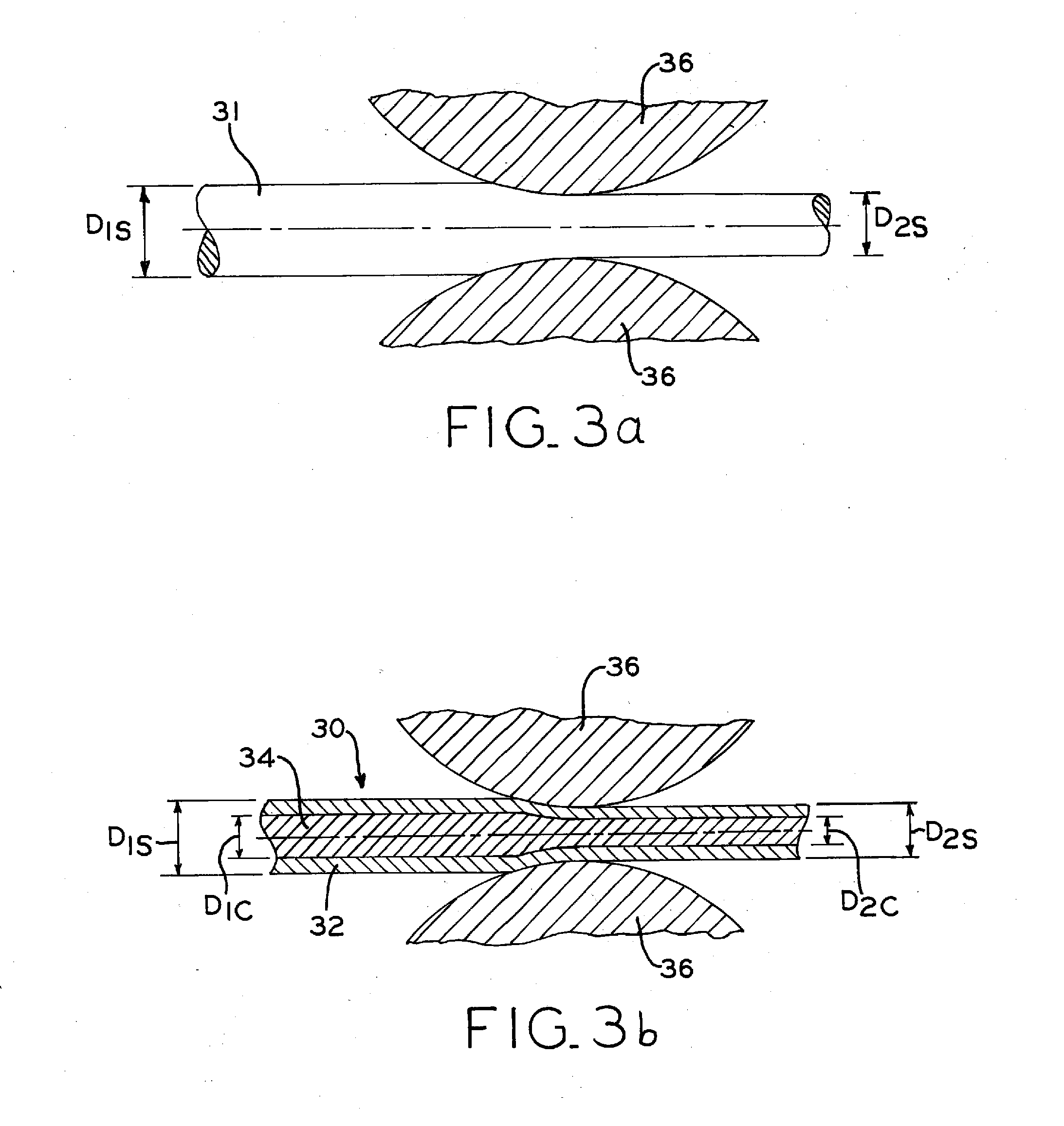
[0147]For Wire #4-6 in Tables 3-2 and 3-4 below, a pure Fe tube of dimension A mm outside diameter (OD)×dimension B mm inside diameter (ID) was filled and drawn down over dimension C mm outside diameter (OD) pure Mg rod to create a first composite having the area fraction specified. Va...


PUM


Abstract

A bioabsorbable wire material includes manganese (Mn) and iron (Fe). One or more additional constituent materials (X) are added to control corrosion in an in vivo environment and, in particular, to prevent and/or substantially reduce the potential for pitting corrosion. For example, the (X) element in the Fe—Mn—X system may include nitrogen (N), molybdenum (Mo) or chromium (Cr), or a combination of these. This promotes controlled degradation of the wire material, such that a high percentage loss of material the overall material mass and volume may occur without fracture of the wire material into multiple wire fragments. In some embodiments, the wire material may have retained cold work for enhanced strength, such as for medical applications. In some applications, the wire material may be a fine wire suitable for use in resorbable in vivo structures such as stents.

Description

CROSS REFERENCE TO RELATED APPLICATIONS[0001]The present application claims the benefit of U.S. provisional patent application Ser. No. 61 / 669,965, filed Jul. 10, 2012 and entitled BIODEGRADABLE ALLOY WIRE FOR MEDICAL DEVICES, the entire disclosure of which is hereby expressly incorporated herein by reference.BACKGROUND[0002]1. Technical Field[0003]The present invention relates to biodegradable wire used in biomedical applications and, in particular, relates to wire alloys with controlled biodegradation for use in medical devices such as stents.[0004]2. Description of the Related Art[0005]Stents are artificial tube-like structures that are deployed within a conduit or passage in the body to alleviate a flow restriction or constriction. Stents are commonly used in coronary arteries to alleviate blood flow restrictions resulting, e.g., from cardiovascular disease. However, stents may also be used in non-coronary vessels, the urinary tract and other areas of the body. Non-coronary appl...

Claims


Application Information

Patent Timeline
IPC IPC(8): A61L31/14A61L31/02C21D8/06C22C38/00C21D9/52C22C38/18C22C38/12C22C38/04A61F2/86C21D6/00
CPCA61L31/148A61F2/86A61L31/022C21D8/065C21D6/002A61F2240/001C21D9/525C22C38/18C22C38/12C22C38/04C22C38/001C21D6/005A61L31/088A61L31/143C21D1/30C21D9/52Y10T29/49934Y10T428/12Y10T428/12729
Inventor SCHAFFER, JEREMY E.
Owner FORT WAYNE METALS RES PROD CORP
Why Eureka
Try Eureka