Plasma-Kinetic Spray Apparatus and Method

a technology of spray apparatus and spray coating, which is applied in the direction of molten spray coating, plasma technique, coating, etc., can solve the problems of limited cold gas dynamic spray method of alkhimov et al, limited use of 1-50 micron size powder particles, and less or greater degree of

Inactive Publication Date: 2015-08-13
FLAME SPRAY IND
View PDF11 Cites 8 Cited by
  • Summary
  • Abstract
  • Description
  • Claims
  • Application Information

AI Technical Summary

Benefits of technology

[0026]The invention accordingly comprises the several steps and the relation of one or more of such steps with respect to the others, and the apparatus embodying features of construction, combination

Problems solved by technology

These extremely high temperature devices operate at 12,000° F. to 16,000° F. to spray materials, which melt at typically under 3,000° F. Overheating is common with adverse alloying and/or excess oxidation occurring.
These problems also occur to a lesser or greater degree during the use of the more recently developed HVOF (high velocity oxy-fuel) processes as well as HVAF (high velocity air-fuel) processes.
In addition, the cold gas dynamic spray method as described by Alkhimov et al, is limited to the use of 1-50 micron size powder particles.
The cold gas dynamic spray method of Alkhimov et al is limited to the use of a particle size range of 1-50 micron.
This limitation has been found by Van Steenkiste et al to be due to the heated main high pressure gas being cooled by injecting into it the cold high pressure carrier gas/powder.
However, the kinetic spray coating method and apparatus of Van Steenkiste et al state an upper limit of the particle size range 106 microns, based on experimental results.
This limits the velocity of the particles

Method used


Image

  • Plasma-Kinetic Spray Apparatus and Method
  • Plasma-Kinetic Spray Apparatus and Method
  • Plasma-Kinetic Spray Apparatus and Method

Examples


Embodiment Construction

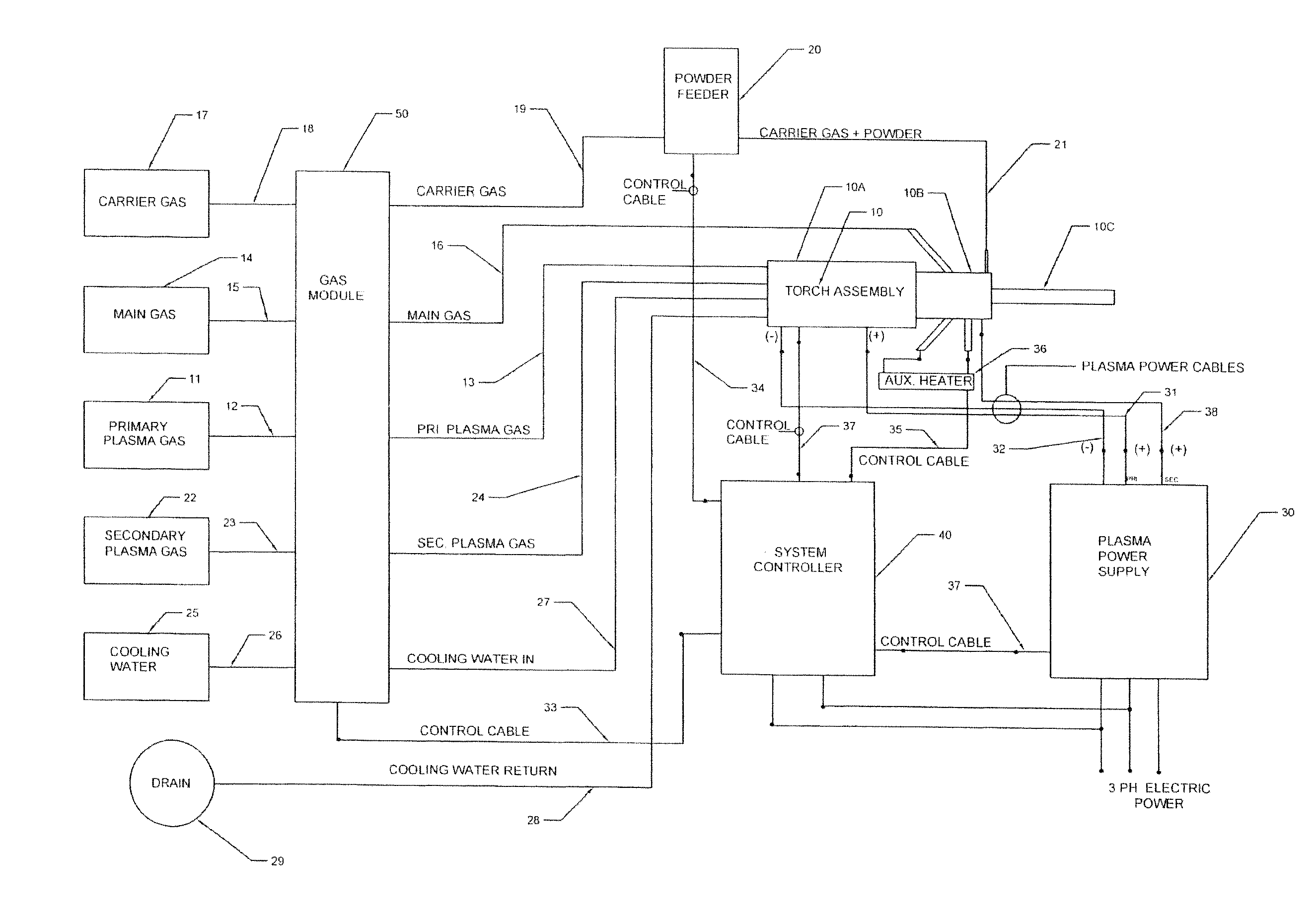
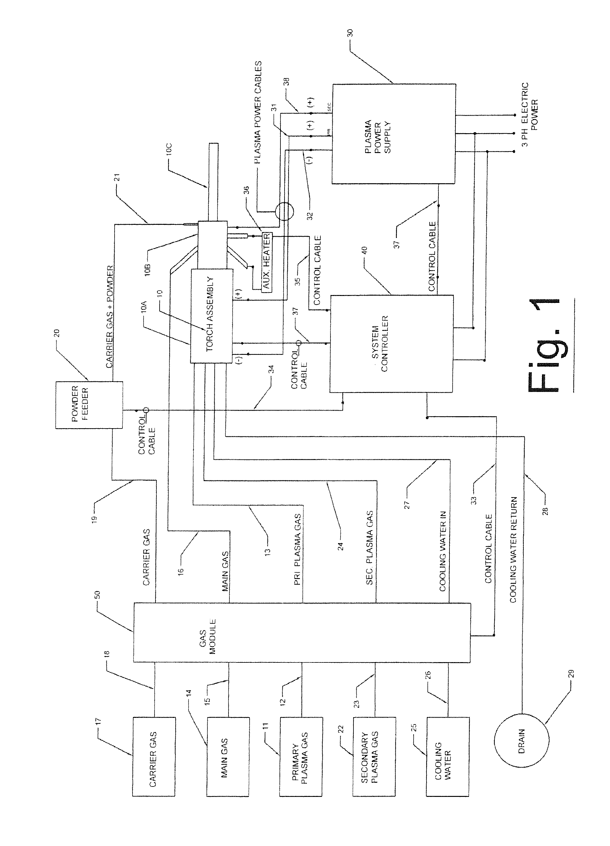
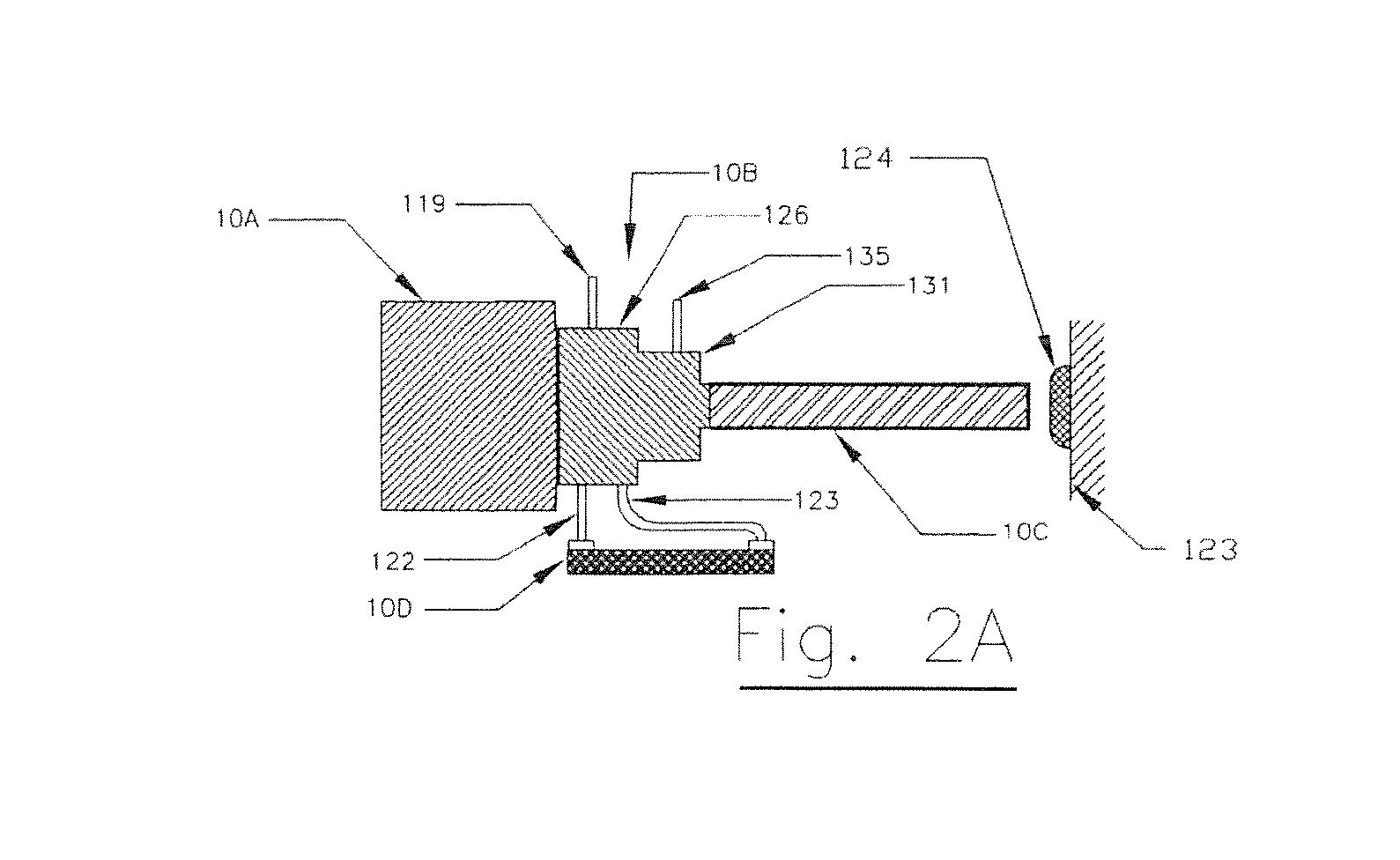
[0033]Generally speaking, preferred embodiments of the present invention provide methodologies and apparatus by which particles of metals, alloys, polymers and mechanical mixtures of the forgoing and with ceramics and semiconductors having a broad range of particle sizes, may be applied to substrates using a novel hybrid plasma / kinetic spray coating method. The present invention includes a hybrid plasma-kinetic torch assembly comprises a two stage transferred-arc plasma generator section, a cold main gas input assembly, followed by an input section for injection of the powder feedstock / carrier gas mixture into the combined plasma gas / cold gas mixture. The final section of the torch assembly includes an accelerating nozzle into which all of the preceding combined gas flows enter into a convergent portion of the accelerating nozzle, through a critical orifice and finally expanded in a divergent section of the nozzle, causing expansion of the gas and simultaneously accelerating the flo...


PUM

PropertyMeasurementUnit
Velocityaaaaaaaaaa

Abstract

A coating system that applies a coating of particles to a surface of an article. The coating system comprises a hybrid plasma torch which may include a cathode, a first plasma gas chamber, a first mixing chamber, a plasma generator for generating an arc column of plasma, a second mixing chamber for mixing a main gas, an at least partially ionized first plasma gas and a second gas that was mixed in the first mixing chamber, wherein the second mixing chamber is dimensioned to receive a plurality of powder particles suspended in a carrier gas, and an accelerator assembly for accelerating the mixture of the main gas, the at least partially ionized first plasma gas, the second plasma gas and the powder particles into a high-velocity stream and for directing the high-velocity stream against the surface of the article. A method of applying the coating of particles is also provided.

Description

FIELD OF INVENTION[0001]The present invention is directed to a method and apparatus for the low temperature, high velocity particle deposition onto a substrate surface utilizing a plasma-kinetic spray apparatus. Moreover, the present invention is an improved thermal spray method and apparatus in which the in-transit temperature of the powder particles is below their thermal softening point and whereas a cohesive coating is formed by conversion of the kinetic energy of the high velocity particles to elastic deformation of the particles upon impact against the substrate surface at supersonic velocities. In a preferred embodiment, the plasma-kinetic spray apparatus is a hybrid plasma-kinetic spray apparatus.BACKGROUND OF THE INVENTION[0002]Until recently it has been the practice with thermal spraying technologies, to use the highest temperature heat sources to spray metal and refractory powders to form a coating on a work piece surface. The highest temperature processes currently in us...

Claims


Application Information

Patent Timeline
IPC IPC(8): C23C4/12B05B7/22
CPCB05B7/226C23C4/127C23C24/04C23C4/134H05H1/42H05H1/34H05H1/3484
Inventor KOWALSKY, KEITH A.BERGHORN, CHRISTOPHER R.MARANTZ, DANIEL R.COOK, DAVID J.CONTI, JOHNSCHNEIDER, RAYMOND M.
Owner FLAME SPRAY IND
Why Eureka
Try Eureka