
Hybrid solar desalination system

The hybrid solar desalination system addresses efficiency and cost challenges by using a hydro-thermal exchange unit and modular design to enhance water production, achieving higher efficiency and competitiveness with conventional methods.

Active Publication Date: 2015-09-03
SUNLIGHT PHOTONICS
View PDF11 Cites 8 Cited by
  • Summary
  • Abstract
  • Description
  • Claims
  • Application Information

AI Technical Summary

Benefits of technology

The system significantly increases water production rates and efficiency, making it more competitive with conventional methods, while being environmentally friendly and economically attractive, with the potential to produce fresh water at a rate ten times higher than existing solar stills.

Problems solved by technology

However, people in many other areas of the world have neither the money nor oil resources to allow them to produce water in a similar manner.
Over a billion people today lack access to purified drinking water and the vast majority of these people live in rural areas, where it is very difficult to implement any traditional clean water solution.
The main drawback with the use of solar energy in existing large-scale desalination plants is the resulting low productivity rate and thermal efficiency.
However, since solar desalination plants use free energy and therefore have insignificant operational costs, over the long term they are more attractive than conventional approaches.
In addition to cost considerations, there are also environmental concerns about the fossil fuel burning.
The low production rate is caused by a low operating temperature and near atmospheric pressure of a resulting steam.
One of the problems that negatively influence the still performance is the direct contact between the collector and the saline water, which may lead to corrosion and scaling in the still.
The biggest issue for the solar stills however are their rather low efficiency and water production rate: a typical production rate of a solar still is about 4 L / m2 / day or less.

Method used


Image

  • Hybrid solar desalination system
  • Hybrid solar desalination system
  • Hybrid solar desalination system

Examples


example 1

[0064]In accordance with the present invention, an apparatus for aeration-assisted mass exchange, e.g. evaporation and condensation, can be provided. It includes a cylindrical container and a disk shaped aerator as shown in FIG. 15. The container can be produced from stainless steel, PVC or other container material suitable for processing of potable water. The diameter of a container may be in the range of 1 cm to 1 m, preferably in the range of 10 to 20 cm, whereas the height of the container may be in the range of 2 cm to 2 m, preferably in the range of 10 to 40 cm. The diameter of the aerator may be about the diameter of the container. The aerator may have a dense array of holes having a diameter in the range of 0.1 to 5 mm, preferably 0.5-2 mm, and the spacing between nearest holes in the range of 0.1 to 5 mm. The apparatus may also include a stack of screens that are made of a stainless steel wire mesh or plastic fibers. Screens may be less than 1mm thick, preferably less than ...

example 2

[0067]In accordance with the present invention, an apparatus for wetscreen-assisted mass exchange, e.g. evaporation and condensation, can be provided. It includes a container and a stack of see-through screens as shown in FIG. 22. The container can be produced from stainless steel, PVC or other container material suitable for processing of potable water. The container may be square in the cross-section having a side size in the range of 1 cm to 1 m, preferably in the range of 10 to 20 cm, whereas the height of the container may be in the range of 2 cm to 2 m, preferably in the range of 10 to 40 cm. The size of the screens may be about the size of the container. The screens may be staggered to provide a passage for the air flow between them, so that some of them have a wide opening for air passage on the right side, while others have an opening on the left side. They may be made of a stainless steel wire mesh, plastic fibers, thin sponge or perforated sheets of other water-safe mater...

example 3

[0070]In accordance with the present invention, an HTS apparatus of a desalination system may be provided as shown in FIG. 9. The apparatus comprises a solar heat collector, an evaporator, a condenser and a heat exchanger. Feed water is provided to the apparatus from a salt or brackish water source, e.g. an ocean or a pond. This water is preheated using a counter-current heat exchanger, e.g. a shell-and-tube heat exchanger produced by Exergy LLC, and then further heated using a solar heat collector, e.g. an FPC panel produced by Schuco USA having an absorber area in the range of 2-3 m2. Multiple collector panels may be used in a single HTS and also, other types of heat collector may be used instead of FPC panels, such as evacuated tubes or concentrated solar collectors. The heated feed water is then fed to the evaporator at a temperature Tin in the range of 50° C. to 100° C., preferably in the range of 80° C. to 99° C. The evaporator may be provided using the apparatus described eit...


PUM

PropertyMeasurementUnit
sizeaaaaaaaaaa
diameteraaaaaaaaaa
heightaaaaaaaaaa

Abstract

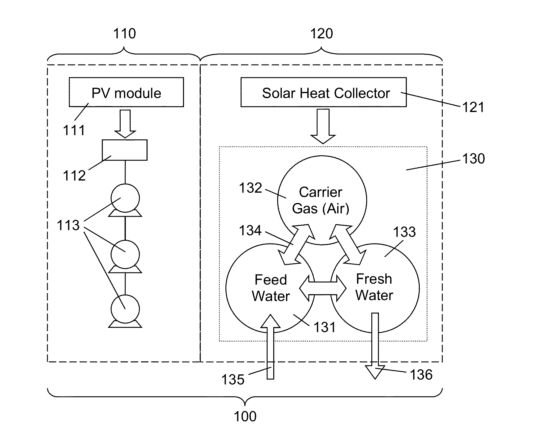
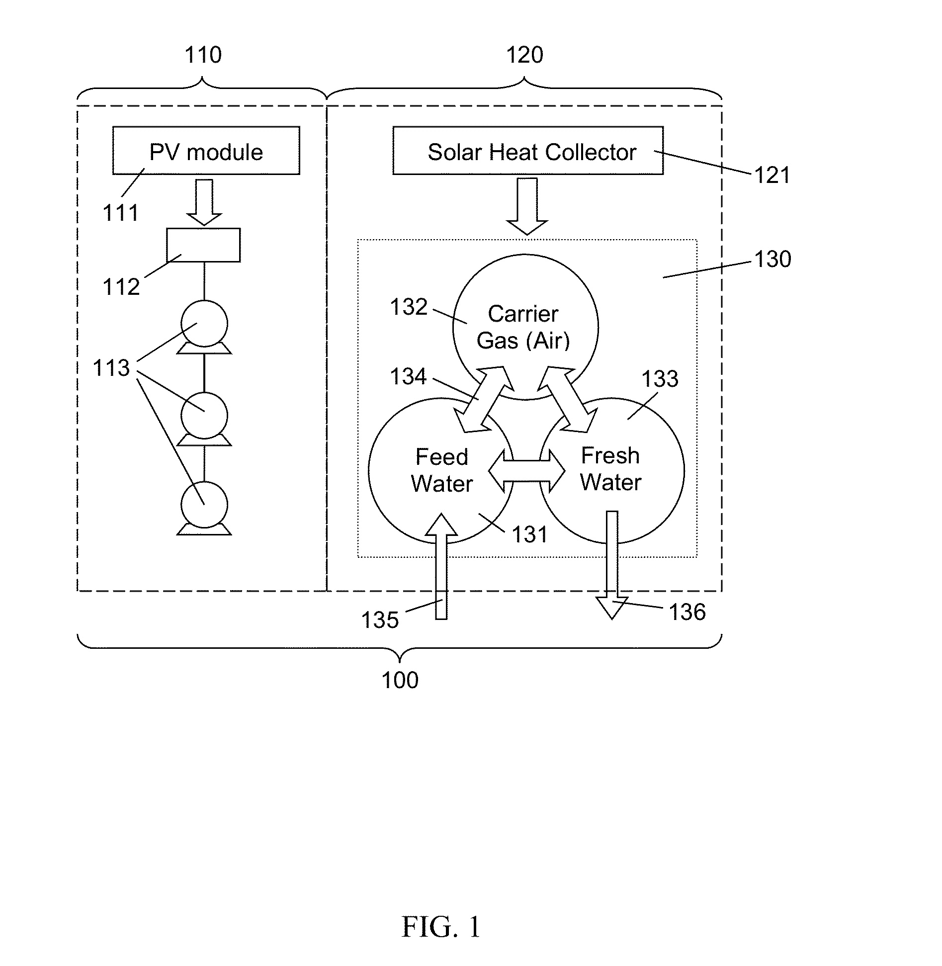
A hydro-thermal exchange unit (HTEU) for desalinating feed water in accordance with a humidification-dehumidification includes feed water, fresh water and gas conduit circuits for transporting feed water, fresh water, and gas, respectively. The unit also includes an evaporator through which a portion of the feed water conduit and the gas conduit pass. The evaporator causes evaporation of a portion of the feed water to produce vapor that is transported through the gas conduit. The unit also includes a condenser through which a portion of the gas conduit and the fresh water conduit pass. The condenser has input and output ports for coupling the gas and fresh water conduit circuits. The condenser extracts moisture from the vapor transported therethrough by the gas conduit. The extracted moisture is discharged through the fresh water conduit. The unit also includes a heat exchanger through which a portion of the fresh water conduit and the feed water conduit pass to thereby extract residual heat from the fresh water such that the residual heat heats the feed water.

Description

CROSS REFERENCE TO RELATED APPLICATION[0001]This application is a divisional of U.S. patent application Ser. No. 13 / 693,932, filed Dec. 4, 2012 entitled “HYBRID SOLAR DESALINATION SYSTEM”, which is a continuation of U.S. Ser. No. 12 / 770,892, filed Apr. 10, 2010, entitled “HYBRID SOLAR DESALINATION SYSTEM”, now abandoned. The subject matter of both applications are incorporated herein by reference.FIELD OF THE INVENTION[0002]The present invention relates generally to a method and apparatus for water desalination using renewable solar energy.BACKGROUND OF THE INVENTION[0003]Fresh water has become a very valuable and scarce resource in recent years not only in arid countries of the Middle East and North Africa regions, but also in many highly populated areas of more developed countries, such as Spain, USA, China and many others. Increases in population and commercial activities have contributed to the depletion of freshwater resources. Desalination, as one of the earliest forms of wate...

Claims


Application Information

Patent Timeline
Patent Type & Authority Applications(United States)
IPC IPC(8): C02F1/14B01D3/00
CPCC02F1/14C02F2103/08B01D3/007B01D1/0047B01D1/14B01D3/16B01D3/343B01D5/0027Y02W10/37Y02A20/124Y02A20/142Y02A20/212
Inventor FROLOV, SERGEYCYRUS, MICHAELBRUCE, ALLAN JAMES
Owner SUNLIGHT PHOTONICS
Learn More