
Process for producing acetic acid

a technology of acetic acid and process, applied in the direction of physical/chemical process catalyst, organic compound/hydride/coordination complex catalyst, separation process, etc., can solve the problems of small concentration of impurities which are difficult to quantitatively determine, adverse effects of impurities, and low quality of acetic acid, so as to achieve high-quality acetic acid, improve acetaldehyde removal efficiency, and high-quality acetic acid

Active Publication Date: 2015-10-22
DAICEL CHEM IND LTD
View PDF0 Cites 14 Cited by
  • Summary
  • Abstract
  • Description
  • Claims
  • Application Information

AI Technical Summary

Benefits of technology

The present invention provides a method of efficiently producing acetic acid with improved acetaldehyde removal. This is achieved by condensing a gaseous phase containing acetaldehyde using multiple condensers to form sequential condensates of decreasing temperature. The result is a highly pure acetic acid with efficient removal of acetaldehyde from the process stream. Additionally, the condensation process results in a liquid-liquid separation of a highly concentrated acetaldehyde-rich aqueous phase and a methyl iodide-containing organic phase, which can be recycled back to the reaction system.

Problems solved by technology

These impurities result in low quality of acetic acid.
Extremely small quantities of reducing impurities present in acetic acid can be evaluated by a permanganate reducing substance test (permanganate time), and this evaluation method detects very small concentrations of impurities which are difficult to determine quantitatively even by a current advanced instrumental analysis.
Moreover, some of these impurities have adverse effects in relation to use of acetic acid.
For example, in a case where vinyl acetate is produced from ethylene and acetic acid, such impurities are known to deteriorate a palladium-series catalyst used.
Unfortunately, a carbonyl compound such as acetaldehyde and a C1-12alkyl iodide cannot be removed sufficiently by an ordinary means such as distillation, due to having boiling points in close proximity.
However, the carbonyl impurity content in the organic stream recycled to the carbonylation reactor is still high, and it is difficult to sufficiently remove the carbonyl impurities.
Accordingly, acetaldehyde cannot be removed efficiently in a process for treating a liquid having a low concentration of acetaldehyde.
Unfortunately, since the absolute quantity of acetaldehyde contained in the exhaust gas is small, acetaldehyde cannot be removed efficiently.

Method used


Image

  • Process for producing acetic acid
  • Process for producing acetic acid
  • Process for producing acetic acid

Examples


example 1

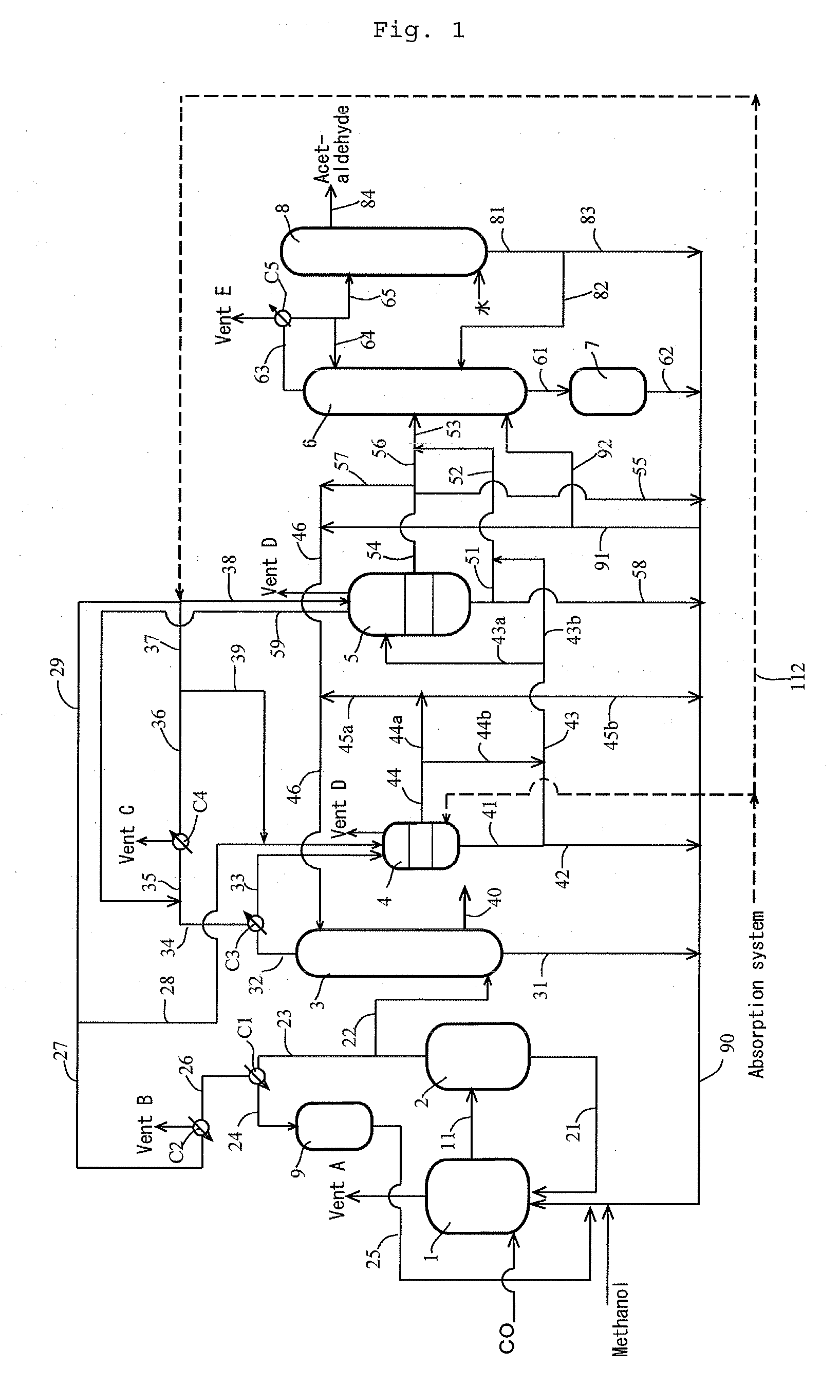
[0184]According to the apparatus (or process) shown in FIG. 1, the process for producing acetic acid was conducted continuously. Specifically, the first overhead (3A) was cooled by the first condenser C3 at a controlled coolant temperature to forma first condensate having a temperature of 38° C. (and a first gaseous component having a temperature of approximately 38° C.). The first gaseous component was cooled by the second condenser C4 at a controlled coolant temperature, and a whole second condensate from the second condenser C4 was fed to the hold tank (which functioned as a decanter when the condensate forms separated liquid phases) 5 via the lines 36 and 38, where the line 36 had a temperature of 12° C., the flow rate in the line 39 was zero “0”. Moreover, the first condensate was fed to the decanter 4 to form an upper layer and a lower layer. The lower layer (lower phase) was fed to the hold tank 5 via the lines 41, 43 and 43a (wherein the flow rate in the line 43b was zero “0...

example 2

[0189]The experiment was carried out in the same manner as in Example 1 except that the temperature of the first condensate was 50° C.

[0190]The composition of the first condensate (in line 43a) fed to the hold tank 5 was as follows: 86.9% by weight methyl iodide, 10.9% by weight methyl acetate, 0.9% by weight acetic acid, 1.0% by weight water, 0.169% by weight acetaldehyde, and 0.001% by weight hydrogen iodide. The composition of the second condensate (in line 38) was as follows: 85.7% by weight methyl iodide, 11.6% by weight methyl acetate, 0.2% by weight acetic acid, 2.0% by weight water, 0.354% by weight acetaldehyde, and 0.001% by weight hydrogen iodide. The feed ratio of the first condensate relative to the second condensate was 84.2% by weight relative to 15.8% by weight. Thereafter, the offgas from the hold tank 5 was recycled to the line 35 via the line 59. The amount (in line 51) of the mixture of the first condensate and the second condensate withdrawn from the hold tank 5...

example 3

[0193]The experiment was carried out in the same manner as in Example 1 except that the temperature of the first condensate was 63° C.

[0194]The first condensate (in line 43a) fed to the hold tank 5 was zero. The composition of the second condensate (in line 38) was as follows: 85.2% by weight methyl iodide, 12.3% by weight methyl acetate, 0.3% by weight acetic acid, 1.8% by weight water, 0.212% by weight acetaldehyde, and 0.001% by weight hydrogen iodide. The feed ratio of the first condensate relative to the second condensate was 0% by weight relative to 100% by weight. Thereafter, the offgas from the hold tank 5 was recycled to the line 35 via the line 59. The amount (in line 51) of the mixture of the first condensate and the second condensate withdrawn from the hold tank 5, that is the amount (in line 53) of the condensate fed to the distillation column 6, was 95% of the total amount (the second condensate (line 38)) fed to the hold tank 5. Moreover, the composition of the conden...


PUM

PropertyMeasurementUnit
temperatureaaaaaaaaaa

Abstract

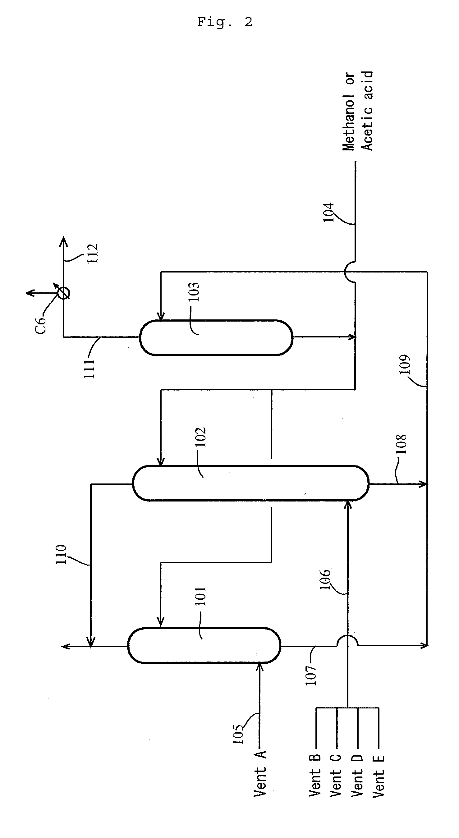
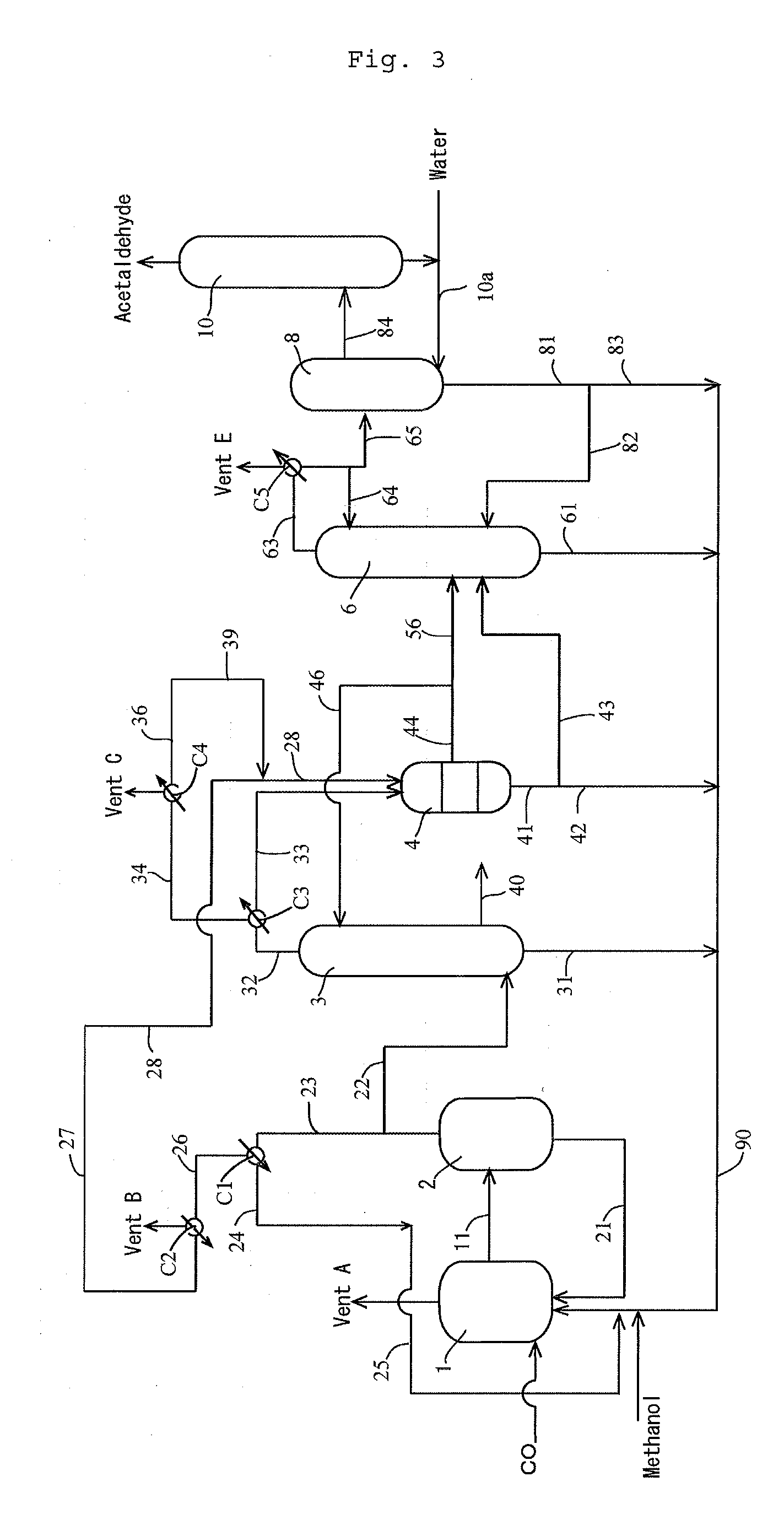
A process for removing acetaldehyde efficiently and producing high-purity acetic acid stably is provided. Methanol is allowed to continuously react with carbon monoxide in a carbonylation reactor 1 in the presence of a catalyst system; the reaction mixture is continuously fed to a flasher 2 to form a volatile phase (2A) containing acetic acid and methyl iodide; the volatile phase (2A) is continuously fed to a splitter column 3 to form an overhead (3A) containing methyl iodide and acetaldehyde and a stream (3B) containing acetic acid; the volatile phase (2A) and / or the overhead (3A) is cooled by a first condenser C1, C3 at a predetermined cooling temperature; and the noncondensed gaseous component is further cooled by a second condenser C2, C4 to form a concentrate having a lower temperature and a higher acetaldehyde concentration. Acetaldehyde is efficiently removed by distilling the concentrate having a high acetaldehyde concentration.

Description

TECHNICAL FIELD[0001]The present invention relates to a process for producing acetic acid by carbonylation of methanol, particularly relates to a process for producing acetic acid with efficiently decreased impurities (e.g., acetaldehyde) and a method for removing acetaldehyde.BACKGROUND ART[0002]Known industrial processes for producing acetic acid include a process which comprises allowing methanol to continuously react with carbon monoxide in a liquid phase having a low water content in the presence of a rhodium catalyst, a metal iodide, and methyl iodide to produce acetic acid with a high productivity. In the reaction liquid, there are small quantities of by-products (impurities), for example, a carbonyl compound (e.g., acetaldehyde, butylaldehyde, crotonaldehyde, 2-ethylcrotonaldehyde, and an aldol condensate thereof) and an organic iodide (e.g., a C2-12alkyl iodide such as ethyl iodide, butyl iodide, or hexyl iodide). These impurities result in low quality of acetic acid. Extre...

Claims


Application Information

Patent Timeline
Patent Type & Authority Applications(United States)
IPC IPC(8): C07C51/12C07C51/44B01D3/40
CPCC07C51/12C07C51/44B01D3/40C07C53/08B01J31/20B01J31/26B01J2231/321B01J2531/822B01J31/16
Inventor SHIMIZU, MASAHIKOSAITO, RYUJIMIURA, HIROYUKI
Owner DAICEL CHEM IND LTD
Learn More