Diffractive lens and optical device using the same

a technology of diffractive lenses and optical devices, applied in the direction of optics, diffraction gratings, instruments, etc., can solve the problems of reducing the pitch between the annuli and degrading machinability, preventing optical performance from being guaranteed, and the effect of reducing the thickness of a thick lens is not expected to be produced, so as to reduce the weight and size of optical devices, reduce the effect of diffraction efficiency and efficiency reduction

Active Publication Date: 2015-12-17
MAXELL HLDG LTD
View PDF4 Cites 10 Cited by
  • Summary
  • Abstract
  • Description
  • Claims
  • Application Information

AI Technical Summary

Benefits of technology

[0023]Claim 10 is characterized by “an optical apparatus using the diffractive lens recited in claim 1” The use of the lens of the present application allows the equivalent refractive lens to be thinned with performance of the refractive lens maintained. This enables a reduction in the weight and size of optical devices in general which use white light, such as cameras, projectors, and lighting devices which use a lens.
[0024]The decrease in diffraction efficiency in the case where the diffractive lens is used for white light as disclosed in JP-A-2001-249271 can be suppressed by eliminating the interference between the adjacent annuli to allow the lens to act as a Fresnel lens and suppress a reduction in efficiency. At this time, the diffractive lens is designed for the use of high-order diffracted light, which enables an increase both in annulus width and in step depth by a factor of the diffraction order compared to the use of first-order diffracted light. This facilitates machining of the mold using the diamond turning tool bit. Furthermore, the lens power can be increased, enabling contribution to the thinning of the lens as is the case with the Fresnel lens.
[0025]The aberration performance in the case wher

Problems solved by technology

However, the need of a high lens power leads to a reduced pitch between the annuli and degraded machinability.
Therefore, such an effect as reducing the thickness of a thick lens is not expected to be produced.
Thus, a wavefront aberration property provided with an optical path length taken into account fails to be ensured, disadvantageously preventing optical performance from being ensured.
However, the pickup lens is expected to be used with monochromatic laser light source, and the diffraction efficiency of the pickup lens disadvantageously decreases with increasing deviation from the blaze wavelength with white light having a wide wavelength range.
Furthermore, the need of a high lens

Method used


Image

  • Diffractive lens and optical device using the same
  • Diffractive lens and optical device using the same
  • Diffractive lens and optical device using the same

Examples


embodiment 1

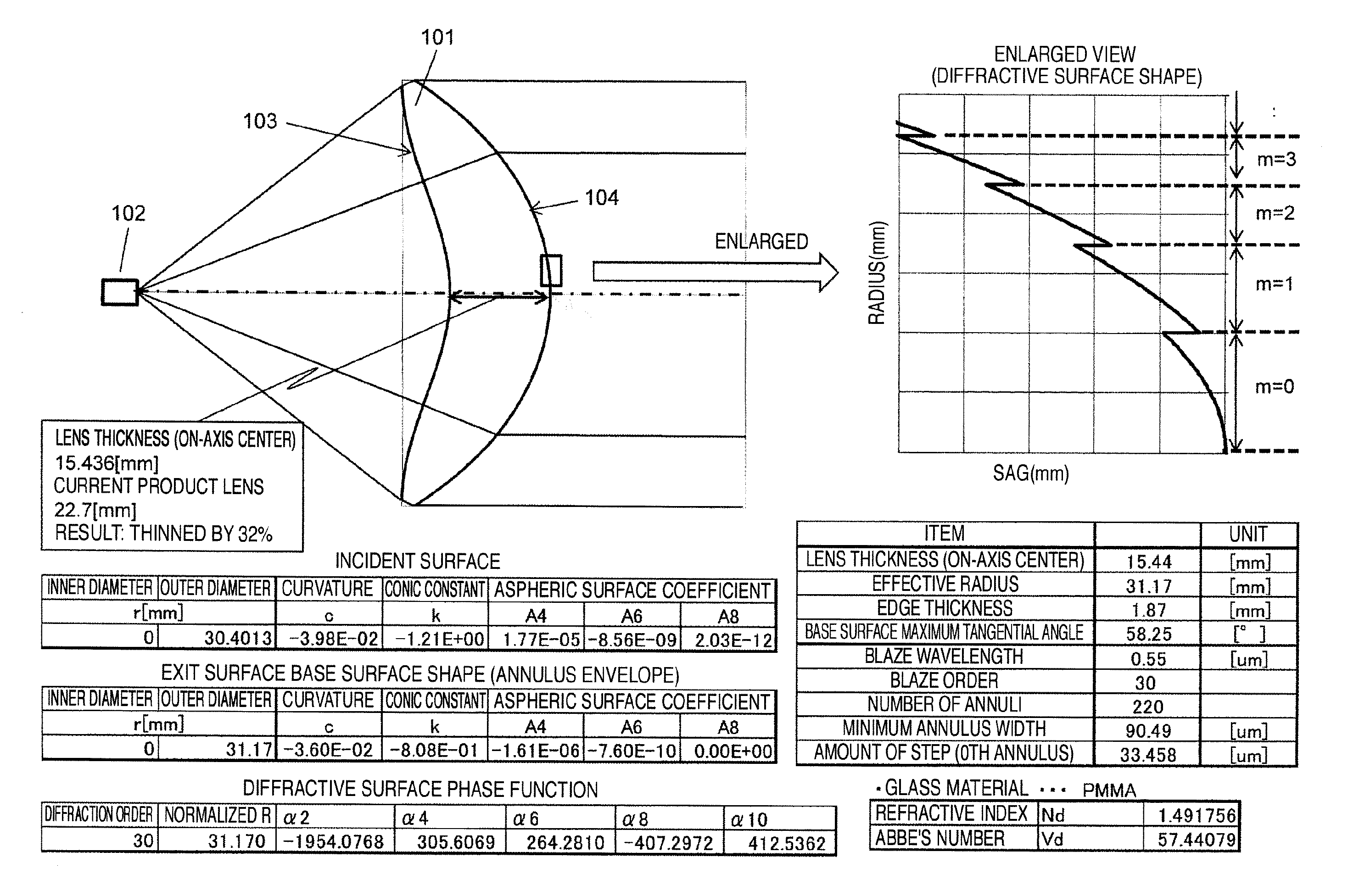
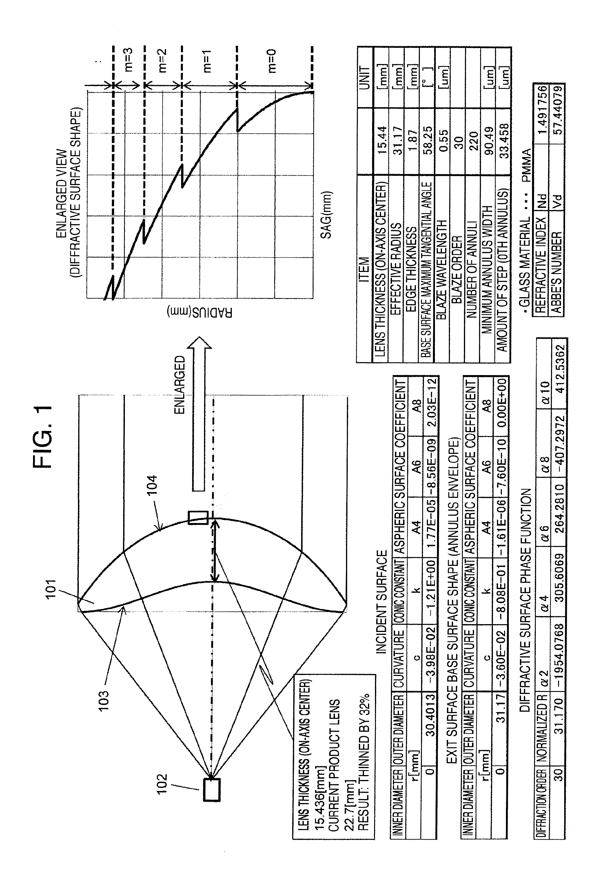
[0042]In the present embodiment, a lens for a lighting optical system will be described which collimates light from a light source and which is assumed to be, for example, a headlamp in an automobile.

[0043]FIG. 1 is a diagram showing an example of the results of design of a diffractive lens in the present embodiment. A diffractive lens 101 is a lens that converts divergence light from a light source 102 into parallel light. A wedge shape is a meniscus lens with an incident surface 103 that is a concave surface and an exit surface 104 that is a convex surface. The lens is a diffractive lens designed to have functions equivalent to the functions of a normal lens shown in FIG. 3 with a focal distance of 57 mm and a diameter of 62 mm. On the exit surface 104, a diffractive lens shape is formed which is provided with axially symmetric annulus areas defined by steps as shown in an enlarged view of a surface shape of a central portion in FIG. 1. A diffraction order is 30th, the number of a...

embodiment 2

[0056]The present embodiment is an embodiment of a lens used for an optical system in a liquid crystal projector which irradiates a liquid crystal modulation element with output light from a LED.

[0057]FIG. 8 is a diagram showing an example of a normal lens that is a model for the present embodiment. This optical system irradiates a diffusion plate surface 804 with light from a monochromatic LED light source 801 via a first lens 802 and a second lens 803. The thicker first lens 802 is replaced with the diffractive lens of the present application by being thinned. A lens material is PMMA, and a lens shape and an on-axis lens thickness are as shown in FIG. 8. A surface shape is described in accordance with an asphericity expression illustrated in Expression 1. These values indicate the first lens has a focal distance of 4.3 mm. FIG. 8 shows one-color LED optical system for simplification. However, in actual use, a wavelength synthesis prism is used between a lens 803 and a diffusion su...


PUM


Abstract

An object of the present application is to thin a thick lens used in an automobile headlamp optical system and a projector lighting optical system while maintaining the optical properties of the lens. A diffractive lens includes, on at least one surface, an optical surface with a plurality of areas defined by a plurality of steps. A blaze wavelength of the diffractive lens is within a wavelength spectral range of a light source used. An optical path difference between adjacent areas at the blaze wavelength is larger than a coherence length of the light source. The diffractive lens substantially acts as a Fresnel lens at a wavelength other than the blaze wavelength.

Description

INCORPORATION BY REFERENCE[0001]The present application claims priority from Japanese application JP-2014-120192 filed on Jun. 11, 2014, the content of which is hereby incorporated by reference into this application.BACKGROUND OF THE INVENTION[0002]The present invention relates to an optical lens used for white light in a camera, a projector, a lighting device, and the like, and an optical device using the optical lens.[0003]JP-A-2001-249271 is a related art in the field of the present invention. JP-A-2001-249271 discloses that “An objective lens 10 is a single lens formed of resin and both surfaces of which are aspheric, and a diffractive lens structure is formed on one lens surface 11 as an annulus-like pattern around an optical axis. At least one of the lens surfaces 11 and 12 is aspheric, and the objective lens 10, in serving as a refractive lens, excessively corrects spherical aberration. The diffractive lens structure is designed to have a predetermined spherical aberration ba...

Claims


Application Information

Patent Timeline
IPC IPC(8): G02B5/18
CPCG02B5/1876G02B5/1895G02B27/425G02B27/4288G02B19/0061
Inventor SHIMANO, TAKESHIKAJIKAWA, HIROYUKI
Owner MAXELL HLDG LTD
Why Eureka
Try Eureka