Lighting circuit and vehicle lamp having the same

a technology of circuit and vehicle lamp, applied in the field of vehicle lamps, can solve the problems of deterioration of laser diodes b>3/b>, excessive energy storage, and similar problems,

Active Publication Date: 2016-03-17
KOITO MFG CO LTD
View PDF13 Cites 27 Cited by
  • Summary
  • Abstract
  • Description
  • Claims
  • Application Information

AI Technical Summary

Benefits of technology

[0040]According to the exemplary embodiments described a

Problems solved by technology

There is a concern that the reliability of the laser diode 3 may deteriorate if supplied with an overcurrent.
However, there is a concern that due to delay in the feedback loop, switching takes places at a large duty ratio immediately before fluctuation of the power source voltage, excessive energy is stored in the inductor, and energy is supplied to the laser diode 3 as an overcurrent.
Such issues do not only arise in boost converters, but may also arise in a circuit system which drives the laser diode 3 using a power source having a topology including an inductor or a transformer, and an output capacitor, such as a buck converter (step down DC/DC converter), a Cuk converter, a Zeta converter, a flyback converter, or a forward converter.
Similar issues may also arise in a circuit system that drives the laser diode 3 using a linear regulator.
However, phase compensa

Method used


Image

  • Lighting circuit and vehicle lamp having the same
  • Lighting circuit and vehicle lamp having the same
  • Lighting circuit and vehicle lamp having the same

Examples


first exemplary embodiment

[0065]FIG. 3 is a circuit diagram of a vehicle lamp 1 according to a first exemplary embodiment. The vehicle lamp 1 includes a light source 2 and a lighting circuit 10 that drives the light source 2.

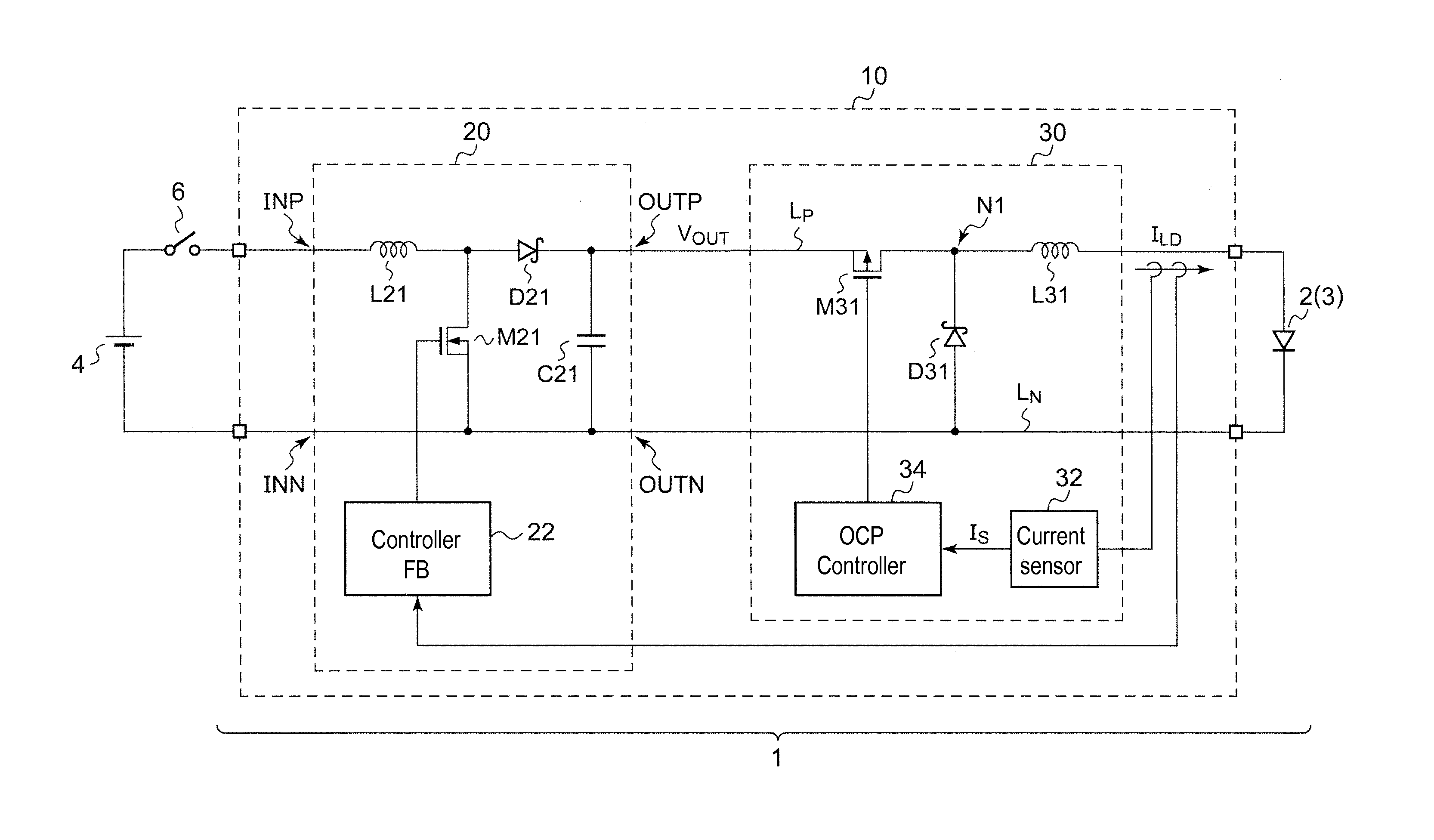
[0066]For example, the light source 2 may include a laser diode 3 and a phosphor (not shown in the drawings). The laser diode 3 emits excitation light. The phosphor emits fluorescent light upon excitation by the excitation light. The light source is configured to generate white output light including spectra of the excitation light and the fluorescent light. Alternatively, the light source 2 may include a white LED, or a combination of red, green, and blue LEDs. When a switch 6 is switched from OFF to ON, the lighting circuit 10 is applied with a voltage VBAT from a battery 4, and steps up and supplies the voltage VBAT to the light source 2.

[0067]The lighting circuit 10 includes a drive circuit 20 and an OCP circuit 30. The drive circuit 20 executes feedback control for the power supplie...

second exemplary embodiment

[0090]FIG. 7 is a circuit diagram of an OCP circuit according to a second exemplary embodiment. An OCP circuit 60 includes a transistor M61, an inductor L61, a rectifier D61, a current sensor 62, and an OCP controller 64. The transistor M61, the inductor L61, and the rectifier D61 are disposed in a T-shape similarly to in the first exemplary embodiment. In the second exemplary embodiment, the transistor M61 and the inductor L61 are provided in series on the path of the power source line LN. A transistor, controlled so as to be switched ON / OFF complementary to the transistor M61, may be used instead of the rectifier D61.

[0091]The current sensor 62 detects the lamp current ILD and generates the current detection signal IS according to the lamp current ILD. The OCP controller 64 controls ON / OFF of the transistor M61 based on the current detection signal IS and the overcurrent threshold value ITH.

[0092]More specifically, in the second exemplary embodiment, if the current detection signa...

third exemplary embodiment

[0108]FIG. 10 is a circuit diagram of a lighting circuit 10 provided with an OCP circuit according to a third exemplary embodiment. An OCP circuit 50 is inserted between a drive circuit 20 and a laser diode 3 in the third exemplary embodiment.

[0109]The OCP circuit 50 includes a current sensor 52, a comparator 54, a timer circuit 56, a bypass transistor M51, and a current restricting resistor R51.

[0110]The current sensor 52 detects a lamp current ILD and generates a current detection signal IS according to the lamp current ILD. The comparator 54 compares the current detection signal IS with the overcurrent threshold value ITH, and generates an asserted (for example, high level) protection signal SOCP when IS>ITH. It is preferable that the comparator 54 is a hysteresis comparator.

[0111]The current restricting resistor R51 is provided on a path of the lamp current ILD. The bypass transistor M51 is provided in parallel to the current restricting resistor R51. The bypass transistor M51 i...


PUM


Abstract

A lighting circuit for a light source includes a drive circuit and an overcurrent protection circuit. The drive circuit supplies power to the light source. The overcurrent protection circuit is inserted between the drive circuit and the light source. The overcurrent protection circuit restricts a lamp current flowing into the light source so that the lamp current does not exceed an overcurrent threshold value. The overcurrent protection circuit includes a transistor, an inductor, a rectifier, a current sensor and an overcurrent protection controller. The current sensor generates a current detection signal according to the lamp current. The overcurrent protection controller controls ON/OFF of the transistor based on the current detection signal and the overcurrent threshold value. The transistor, the inductor and the rectifier are disposed in a T-shape.

Description

CROSS REFERENCE TO RELATED APPLICATION(S)[0001]This application is based on and claims priority under 35 U.S.C. §119 to Japanese Patent Application Nos. 2014-187991 (filed on Sep. 16, 2014), 2014-263103 (filed on Dec. 25, 2014) and 2015-147799 (filed on Jul. 27, 2015), the entire contents of which are incorporated herein by reference.BACKGROUND[0002]1. Field[0003]Exemplary embodiments of the invention relate to a vehicle lamp for use in an automobile or the like, and in particular relate to an overcurrent protection circuit.[0004]2. Related Art[0005]Hitherto, halogen lamps and high intensity discharge (HID) lamps have prevalently been used as light sources for vehicle lamps, and in particular for headlamps. Recently, the development of semiconductor light sources, such as light emitting diodes (LEDs) is progressing as an alternative.[0006]For example, JP 2004-140885 A (corresponding to US 2004 / 0070374 A1) describes a vehicle lamp that includes a laser diode (also referred to as a “s...

Claims


Application Information

Patent Timeline
IPC IPC(8): H05B37/03B60Q1/00H05B44/00
CPCB60Q1/0088H05B37/03B60Q11/005Y02B20/30H05B45/38H05B47/25H05B45/39B60Q1/1415
Inventor ICHIKAWA, TOMOYUKI
Owner KOITO MFG CO LTD
Why Eureka
Try Eureka