Wavelength conversion device, manufacturing method thereof, and related illumination device

a technology of wavelength conversion and manufacturing method, which is applied in the direction of lighting and heating apparatus, instruments, optical elements, etc., can solve the problems of dielectric protection layer being damaged during stamping process, drastic reduction of reflectivity and thermal stability of high reflectivity layer, and reducing reflectivity. , the effect of high thermal conductivity

Active Publication Date: 2016-05-05
APPOTRONICS CORP LTD
View PDF19 Cites 32 Cited by
  • Summary
  • Abstract
  • Description
  • Claims
  • Application Information

AI Technical Summary

Benefits of technology

[0038]Compared with conventional technologies, the embodiments of the present invention have the following advantages:
[0039]In embodiments of the present invention, the wavelength conversion device uses a diffuse reflection layer and a high thermal conductivity substrate to replace the mirror-surface aluminum substrate of the conventional technology. The diffuse reflection layer includes white scattering particles, which can scatter incident light, so that the mirror reflection of the conventional metal reflective layer is replaced with a diffuse reflection process to achieve reflection of the incident light. Moreover, even at high temperature, the white scattering particles will not be oxidized and become absorbent of the incident light. Therefore, even at high temperature, the diffuse reflection layer will not have reduced reflectivity, making the device high temperature resistant. Meanwhile, because the high thermal conductivity substrate is one of aluminum nitride, silicon nitride, silicon carbide, boron nitride, and beryllium oxide, the melting points of these ceramic materials are much higher than that of metal aluminum, so they can withstand higher temperature than aluminum. As a result, the wavelength conversion device according to embodiments of the present invention can withstand high temperature.

Problems solved by technology

This type of mirror-surface aluminum plate has two problems.
First, the thermal expansion coefficients of the surface dielectric protection layer and the high reflectivity layer do not match, so the dielectric protection layer tends to be damaged during the stamping process, or even fall off.
Second, for the high reflectivity silver layer which has a higher reflectivity, under high temperature, a gap may form between the dielectric protection layer and the high reflectivity layer, so that the high reflectivity layer comes into contact with the air; the silver atoms tend to react with the hydrogen sulfide or oxygen in the air in a sulfidation or oxidation reaction, which results in drastic reduction in the reflectivity and thermal stability of the high reflectivity layer.
For an aluminum reflective layer, the thermal stability of aluminum is better than silver, but its reflectivity is not high enough.
Therefore, under current fabrication conditions, mirror-surface aluminum substrate cannot withstand high temperature, and is not suitable for high power light emitting devices.

Method used


Image

  • Wavelength conversion device, manufacturing method thereof, and related illumination device
  • Wavelength conversion device, manufacturing method thereof, and related illumination device
  • Wavelength conversion device, manufacturing method thereof, and related illumination device

Examples


Embodiment Construction

[0046]Embodiments of the present invention are described below with reference to the drawings.

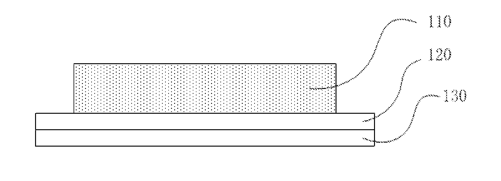
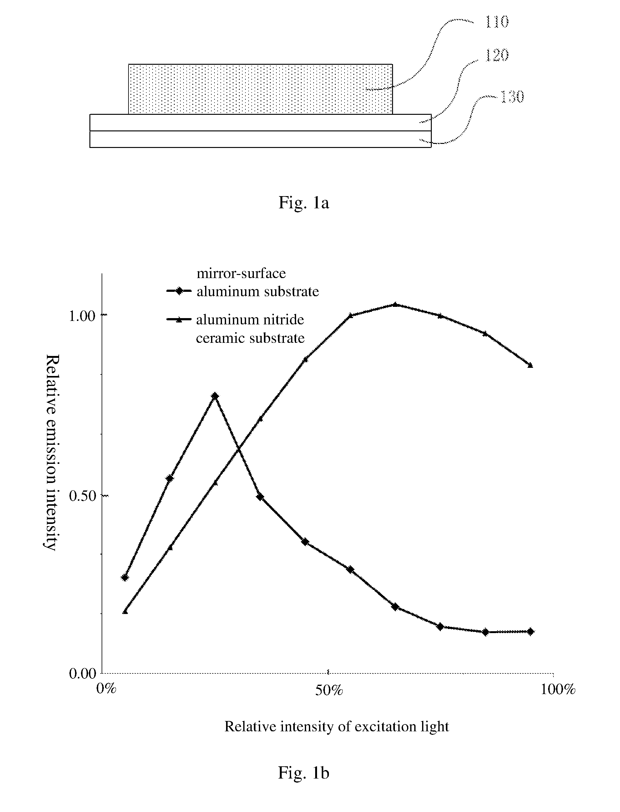
[0047]Refer to FIG. 1a, which schematically illustrates the structure of a wavelength conversion device according to an embodiment of the present invention. As shown in FIG. 1a, the wavelength conversion device includes a phosphor layer 110, a diffuse reflection layer 120, and a high thermal conductivity substrate 130, which are sequentially stacked and affixed together.

[0048]The phosphor layer 110 includes a phosphor powder. The phosphor powder absorbs an excitation light and is excited by it to generate a converted light having a wavelength different from that of the excitation light. For example, YAG (yttrium aluminium garnet) phosphor can absorb blue and UV excitation light to generate a yellow converted light. The phosphor powder may also be a red phosphor, a green phosphor, etc.

[0049]The diffuse reflection layer 120 reflects the incident light. It includes white scattering particles. ...


PUM

PropertyMeasurementUnit
softening pointaaaaaaaaaa
melting pointaaaaaaaaaa

Abstract

A wavelength conversion device, a manufacturing method thereof, and a related illumination device. The wavelength conversion device comprises a fluorescent powder layer (110) that is successively stacked, a diffuse reflection layer (120), and a high-thermal-conductivity substrate (130). The diffuse reflection layer (120) comprises white scattered particles for scattering the incident light; the high-thermal-conductivity substrate (130) is one of an aluminum nitride substrate, a silicon nitride substrate, a silicon carbide substrate, a boron nitride substrate, and a beryllium oxide substrate. The wavelength conversion device has good reflectivity and thermal stability.

Description

BACKGROUND OF THE INVENTION[0001]1. Field of the Invention[0002]This invention relates to illumination and display technologies, and in particular, it relates to a wavelength conversion device, a manufacturing method thereof, and a related light emitting device.[0003]2. Description of Related Art[0004]Using laser or LED as a light source to excite a phosphor material to obtain monochromatic light or polychromatic light is a widely used technology in illumination, projection and other application fields. Such technologies typically direct a light emitted by the laser or LED onto a phosphor color wheel which rotate at a high speed, to achieve good heat dissipation.[0005]Color wheels in existing technologies include a two layer structure, where the lower layer is an aluminum substrate with a mirror surface, and the upper layer is a phosphor layer over the aluminum substrate.[0006]The mirror-surface aluminum substrate primarily functions to reflect light and conduct heat. The mirror-sur...

Claims


Application Information

Patent Timeline
Patent Type & Authority Applications(United States)
IPC IPC(8): F21V9/16F21V29/70F21V29/505F21V13/08F21V9/40
CPCF21V9/16F21V29/505F21V29/70F21V13/08F21V7/22G03B21/16G03B21/204G02B5/0242G02B5/0284G02B5/0808G02B7/181C09K11/02C03C8/14C09K11/08F21V9/30C04B41/89C04B41/5022C04B41/5032C04B41/009
Inventor XU, YANZHENGTIAN, ZIFENGLI, QIANXU, HU
Owner APPOTRONICS CORP LTD
Why Eureka
Try Eureka