Control of solidification in laser powder bed fusion additive manufacturing using a diode laser fiber array

a laser fiber array and laser powder bed technology, applied in the direction of blade accessories, crystal growth process, machine/engine, etc., can solve the problems of cracking of certain alloys, difficulty in obtaining desirable grain, and building can take days to process

Active Publication Date: 2016-06-09
GENERAL ELECTRIC CO
View PDF1 Cites 135 Cited by
  • Summary
  • Abstract
  • Description
  • Claims
  • Application Information

AI Technical Summary

Problems solved by technology

For some applications, the build can require days of processing time.
Another problem of laser scanning Direct Metal Laser Melting (DMLM) systems is rapid cooling rates that can lead to cracking of certain alloys during the additive manufacturing build process.
Rapid cooling rates also present difficulties in obtaining desirable grain morphology, pattern and size, for example equiaxed or columnar grains, grain growth that is normal to the layer surface.

Method used


Image

  • Control of solidification in laser powder bed fusion additive manufacturing using a diode laser fiber array
  • Control of solidification in laser powder bed fusion additive manufacturing using a diode laser fiber array
  • Control of solidification in laser powder bed fusion additive manufacturing using a diode laser fiber array

Examples


Embodiment Construction

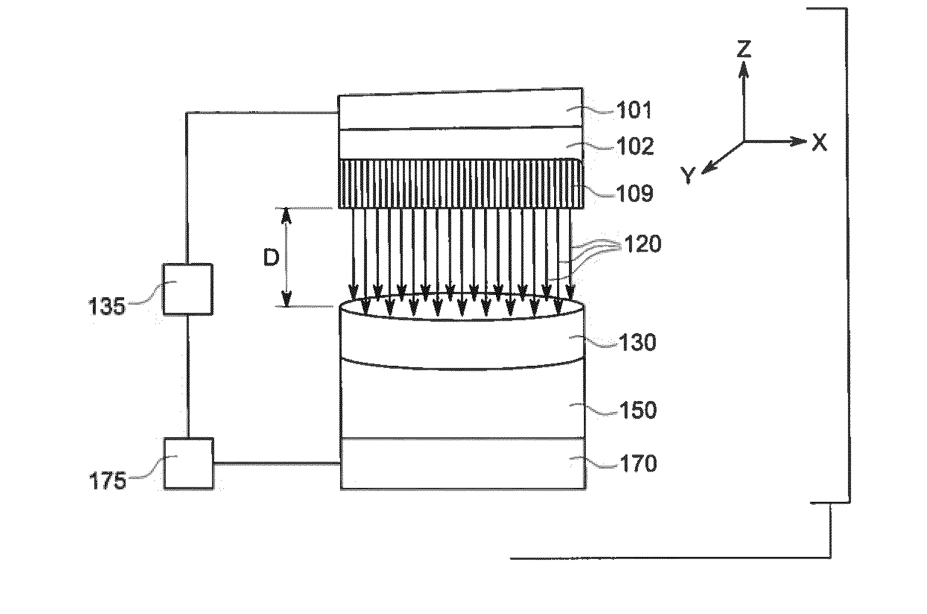
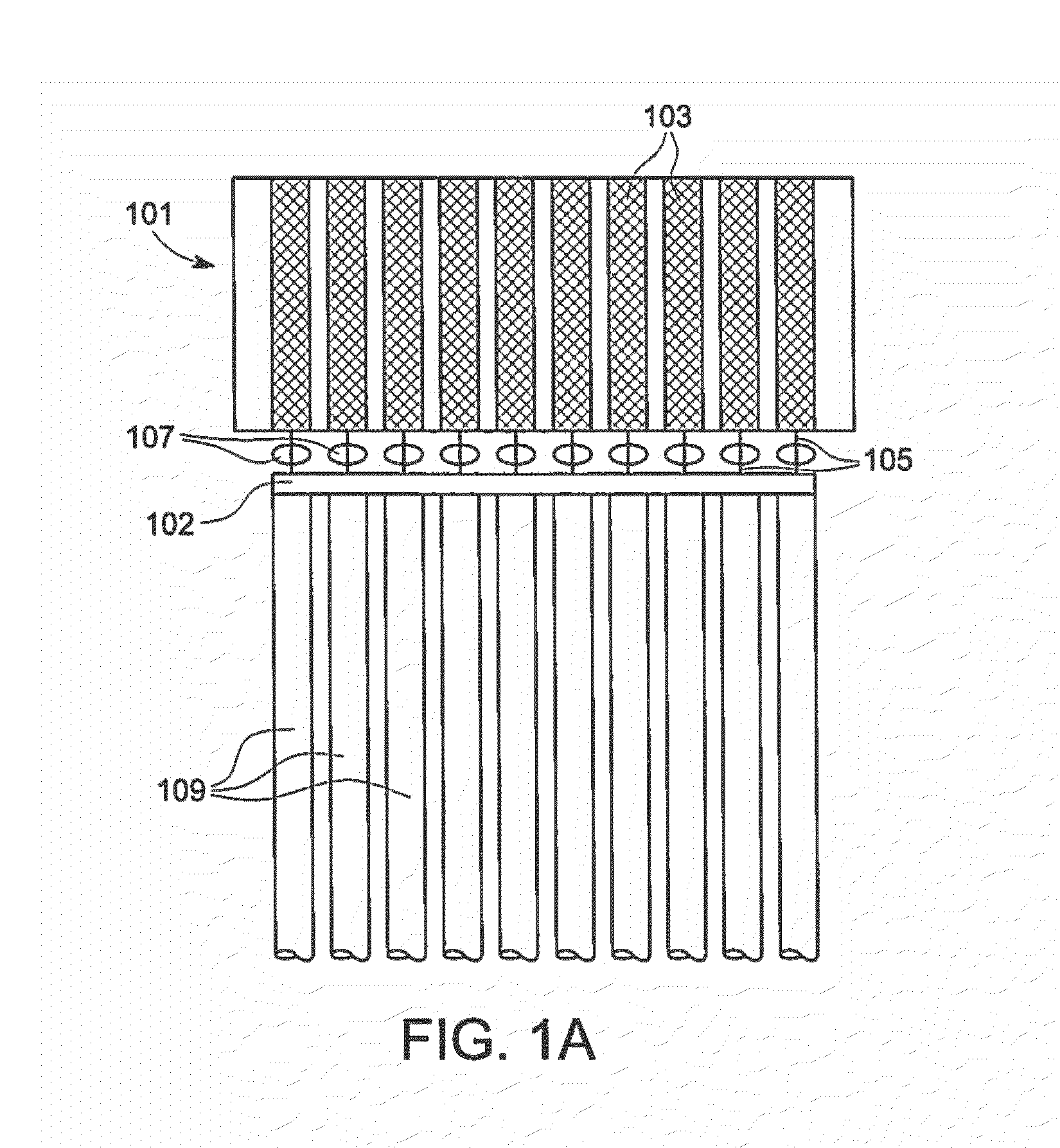
[0017]Referring to FIG. 1A, a diode laser array 101 (e.g., a diode laser bar, fiber pigtail, or stack) includes a plurality of diode lasers, or emitters, 103, each emitting a beam of laser energy 105. A plurality of spherical lenses 107 are positioned between the diode lasers 103 and a plurality of optical fibers 109 to couple laser energy from each diode laser 103 to an optical fiber 109. The optical fibers 109 may be provided in a bundle 102 between the diode lasers and the free ends of the optical fiber array, as shown for example in FIGS. 1A-1C. However, it should be appreciated that diode fiber laser arrays that do not use coupling optics may be used with the present technology, as discussed below.

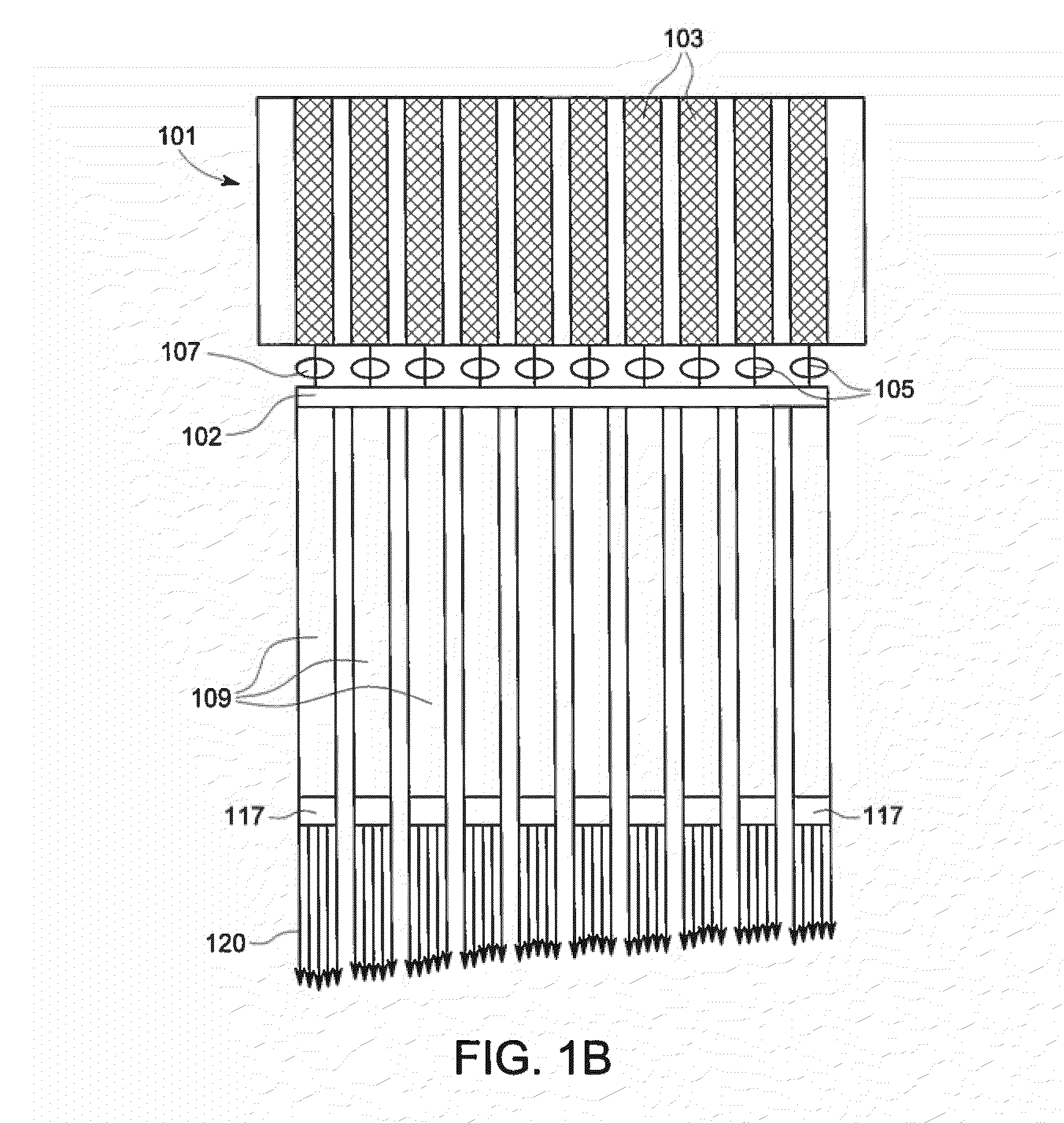
[0018]Referring to FIG. 1B, the diode laser fiber array 101 may include lenses 117 at the ends of the optical fibers 109. The lenses 117 may be configured to provide collimated laser beams 120 from the optical fibers 109. Referring to FIG. 1C, the diode laser fiber array 101 may not i...


PUM

PropertyMeasurementUnit
diameteraaaaaaaaaa
particle sizeaaaaaaaaaa
thicknessaaaaaaaaaa

Abstract

A method of method of forming or repairing a superalloy article having a columnar or equiaxed or directionally solidified or amorphous or single crystal microstructure includes emitting a plurality of laser beams from selected fibers of a diode laser fiber array corresponding to a pattern of a layer of the article onto a powder bed of the superalloy to form a melt pool; and controlling a temperature gradient and a solidification velocity of the melt pool to form the columnar or single crystal microstructure.

Description

BACKGROUND[0001]The present technology relates generally to the use of a diode laser fiber array for laser powder bed fusion additive manufacturing, for example Direct Metal Laser Melting (DMLM), for use in the fabrication or repair of components, more particularly components of a gas turbine engine.[0002]Additive manufacturing is a known technology that enables the “3D-printing” of components of various materials including metals, ceramics and plastics. In additive manufacturing, a part is built in a layer-by-layer manner by leveling metal powder and selectively fusing the powder within a layer using a high-power laser or electron beam. After each layer, more powder is added and the laser patterns the next layer, simultaneously fusing it to the prior layers to fabricate a complete component buried in a powder bed. Additive manufacturing systems and processes are used to fabricate precision three-dimensional components from a digital model.[0003]In making a build in current powder b...

Claims


Application Information

Patent Timeline
Patent Type & Authority Applications(United States)
IPC IPC(8): B23K26/342B22F1/00B23K26/0622B23K26/06B23K26/00B23P6/00
CPCB23K26/342B23K26/0006B23P6/007B23K26/0622B22F2301/15B22F1/0003B23K2203/08B33Y10/00B33Y80/00B23K26/0617B22F5/009B23K26/0608B23K26/073B28B1/001B29C73/00B23K26/34B29C73/34B29K2105/251F05D2230/31B29L2031/08B33Y30/00F01D5/005B22F5/04B22F2999/00C30B11/005C30B11/006C30B11/007C30B13/06C30B13/24C30B13/30C30B13/32C30B29/52B29C64/153B23K2101/001B23K2103/26G02B6/425G02B6/4268Y02P10/25B22F12/41B22F10/38B22F12/44B22F10/28B22F10/36B22F10/368B22F10/362B22F12/45B22F2304/10B22F2207/15
Inventor CARTER, WILLIAM THOMASJONES, MARSHALL GORDONYUAN, LANGZHOU, NINGDUCLOS, STEVEN JUDE
Owner GENERAL ELECTRIC CO
Why Eureka
Try Eureka