Photon count-based radiation imaging system, method and device thereof

Active Publication Date: 2016-09-15
NANOVISION TECHNOLOGY (BEIJING) CO LTD
View PDF2 Cites 45 Cited by
  • Summary
  • Abstract
  • Description
  • Claims
  • Application Information

AI Technical Summary

Benefits of technology

[0077](4) the system is miniaturized and i

Problems solved by technology

This is very adverse for medical diagnosis.
This has missed the best time to treatment, seriously affecting the patients' chances of recovery.
(1) Crystal interference contrast-imaging method: A complete crystal is cut into three very thin 3L shapes with bases connected together, which are respectively a beam splitter, a projection crystal and an analysis crystal. An X-ray is incident and passes through the first crystal, and then is diffracted and separated into two beams of coherent light. One beam of light is used as reference light, and a phase changer is placed on a propagation path thereof to continuously change light. The method is relatively strict in demanding mechanical stability of the experiment device; as a final diffraction pattern is detected after the incident X-ray penetrates 3 layers of crystals, the photon utilization is low, and a strong light source or a longer exposure time is required to make up. As the crystal size is limited, the method is only suitable for some small-size samples, and is only applicable to synchronous radiation at present.
(2) Crystal diffraction enhancement method: after heterogeneous X-rays emitted by the X-ray source go through a complete crystal, X-rays of which the incident angle meets the bragg diffraction condition (that is, the condition of producing coherent light interference) can pass through a monochromatic crystal, thus forming monochromatic light. An analysis crystal is placed behind the sample to serve as an angle analyzer, followed by a detector to record images. After the monochromatic light penetrates the sample, the analysis crystal converts phase information to light intensity information. By using the analysis crystal and adjusting the angle of the analysis crystal, X-rays transmitted, refracted and small-angle scattered after passing through the sample are enhanced or weakened, and thus diffraction enhancement imaging has three mechanisms of producing contrast, which are respectively absorption contrast, refraction contrast and extinction contrast obtained by filtering small-angle sc

Method used


Image

  • Photon count-based radiation imaging system, method and device thereof
  • Photon count-based radiation imaging system, method and device thereof
  • Photon count-based radiation imaging system, method and device thereof

Examples


Example

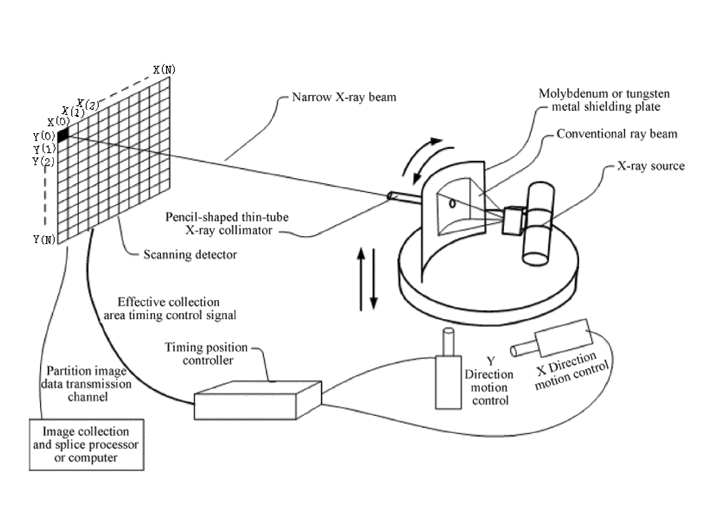
[0121]Embodiment 1 of the present invention provides a photon count-based radiation imaging system, as shown in FIG. 9, the radiation imaging system includes an X-ray source, a scanning platform for bearing a sample, a photon count detector, a three-dimensional reconstruction system and other components. The X-ray source is a micro-focus near monochromatic light source, used for emitting an X-ray to the sample on the scanning platform. After an X-ray is filtered by a filter, a near monochromatic X-ray is obtained and irradiated onto a tested sample. After the X-ray penetrates the sample, physical phenomena such as absorption, reflection, refraction, transmission, phase shift and the like may be generated, and lots of photons carrying material information in particular spatial positions are generated in an imaging plane. The photon count detector is used for counting photons in the imaging plane, so as to obtain projection data and energy data of incident photons, and transmits the p...

Example

Embodiment 2

[0148]In the X-ray imaging technology, a low-power-consumption micro-focus X-ray source is used, has enough coherence, but has a too narrow light beam and too small luminous flux, and the detector requires a quite long exposure time, which is limited to be extent during clinical application. As shown in FIG. 18, the present invention uses a grating self-imaging effect to design a light path, to cause an image of a first phase grating to match a second absorption grating, and then analyzes moire fringes formed by the sample, which can quantitatively recover a wave front. So, the present invention no longer relies on high-brightness and higher-coherence synchronous radiation light sources.

[0149]To this end, Embodiment 2 of the present invention provides a photon count-based radiation imaging system, and uses the photon count technology and the grating imaging technology to solve technical defects of the prior art. As shown in FIG. 19, it is an overall schematic structural ...

Example

Embodiment 3

[0197]As the grid of the X-ray source in the prior art has the following shortcomings: on the one hand, as the focal point of the grid is fixed, imaging requirements for different parts cannot be met, and the imaging quality is seriously affected; on the other hand, the grid per se also blocks some X-rays that should be shot to the photon count detector. In order to eliminate such adverse effects, radiation dose of the X-ray must be increased, which causes more radiation to tested objects especially patients and medical staff, increases the manufacturing cost of the photon count detector, and brings about difficulty to environmental protection work of the hospital.

[0198]As the virtual grid technology in the prior art does not filter scattered rays reaching the photosensitive plane of the photon count detector, scattered ray and straight ray data are all sampled. For the thick position radiography where scattered rays take a greater proportion, minor details of the straig...


PUM


Abstract

A photon count-based radiation imaging system. The invention also relates to a method of implementing X-ray imaging in said system, and to key apparatus of said system. In the system, an x-ray source directs x-rays at a sample on a scanning platform. When the x-rays pass through said sample, photons carrying information about characteristics of the material at various spatial positions are produced. A photon count detector counts the photons on an imaging plane, obtains incident photon projection data and energy data, and transmits same to a 3D reconstruction system. The 3D reconstruction system reconstructs, on the basis of said projection data and energy data, the 3D structure and the matter composition inside the sample, then performs digital dyeing on the component parts of the sample, thereby differentiating the matter composition of the sample.

Description

BACKGROUND[0001]1. Technical Field[0002]The present invention relates to a radiation imaging system, particularly to a photon count-based X-ray imaging system, and also to a method for achieving X-ray imaging by the system and key devices thereof, which belong to the field of medical image technologies.[0003]2. Related Art[0004]The penetrating power of X-rays is particularly strong. When the X-rays pass through a sample made up of light elements such as carbon, hydrogen and oxygen, they leave no observable traces like visible light penetrates glass. This is very adverse for medical diagnosis. For example, for the diagnosis of breast tumor, the breast tumor, in the early stage of the development, is still the focus composed of light elements, the absorption-contrast imaging is helpless, and it is visible to the absorption-contrast imaging until calcification is generated in the late stage of the development of the breast tumor. This has missed the best time to treatment, seriously af...

Claims


Application Information

Patent Timeline
IPC IPC(8): G01N23/083A61B6/00G21K1/02A61B6/03G01N23/04G21K1/06
CPCG01N23/083G01N23/046G21K1/06G21K1/02G01N2223/501A61B6/4241A61B6/484G01N2223/419A61B6/032A61B6/03A61B6/502A61B6/52G01T1/24G21K1/025G21K2207/005H01J35/08H01J35/14H01J35/116G01N23/087G01T1/247G01T1/36
Inventor CAO, HONGGUANGLI, YUNXIANGZHENG, HAILIANG
Owner NANOVISION TECHNOLOGY (BEIJING) CO LTD
Why Eureka
Try Eureka