
Ceramic coating and process for applying the same

a ceramic coating and coating technology, applied in the direction of superimposed coating process, coating, lighting and heating apparatus, etc., can solve the problems of aggravated wear through the tube walls, the life of boiler tubes is generally relatively short, and the replacement of complete tube stacks or panels is known to be difficult, so as to reduce corrosion and erosion

Inactive Publication Date: 2016-10-20
FIRESIDE COATINGS INC
View PDF0 Cites 4 Cited by
  • Summary
  • Abstract
  • Description
  • Claims
  • Application Information

AI Technical Summary

Benefits of technology

The present invention is about a ceramic coating for fireside boiler tubing that can protect against corrosion and erosion caused by burning corrosive or erosive fuels. The coating is a dual color sprayed-on composite ceramic coating that acts as a visual inspection aid, allowing for fast application rates and reduction of equipment downtime. The coating is formulated to withstand severe thermal cycling and has high mechanical bonding, erosion and corrosion resistance, as well as high emissivity and thermal conductivity. It can also be re-applied quickly and without removing any existing ceramic coating.

Problems solved by technology

Boiler tubes generally have a relatively short life due to corrosion and erosion problems which exist in high temperature boilers.
The high boiler temperatures together with the flow of hot gases carrying particles, soot and other wear and erosion-causing materials generally result in aggravated wear through the tube walls.
Complete tube stacks or panels have been known to require replacement in a matter of months.
The protective coatings used vary, but they all must periodically be reapplied once the coating has corroded and / or eroded to an unsafe condition.
The only way to determine the remaining coating thickness is to shut down the boiler, then construct scaffolding and measure the remaining coating with a magnetic lift off device, which is costly and time consuming especially if all surfaces are measured and evaluated to determine high erosive and / or corrosive areas.
During removal of these deposits, the protective coating may be thinned or damaged.

Method used

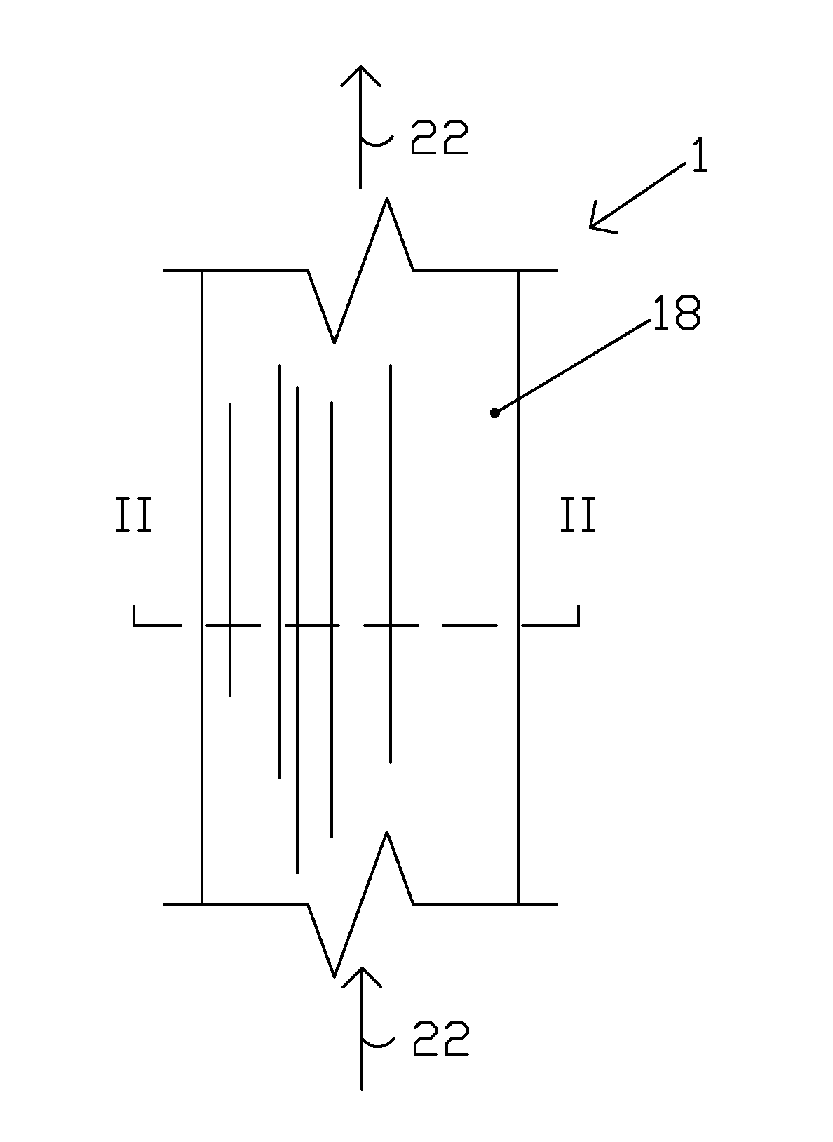
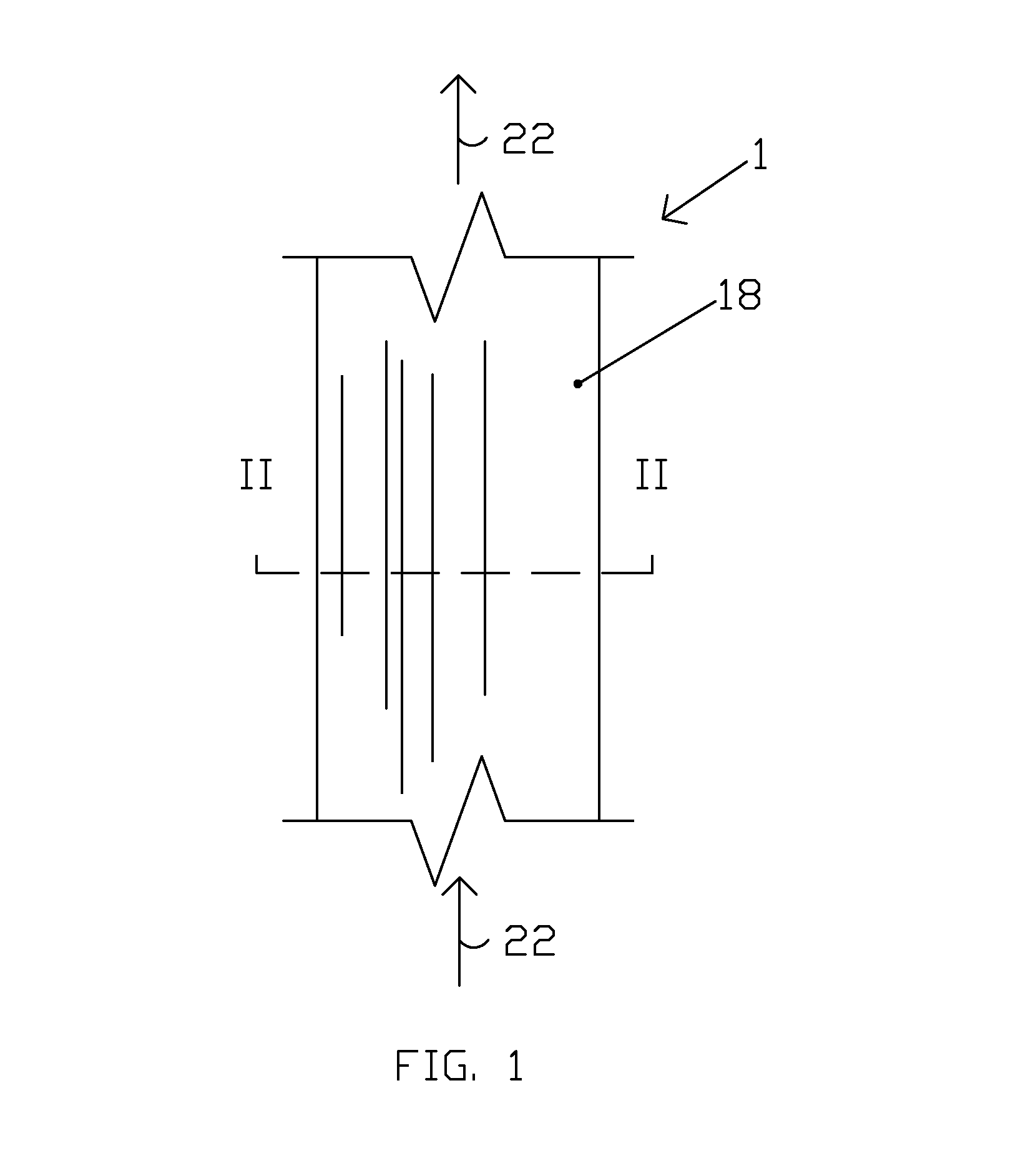
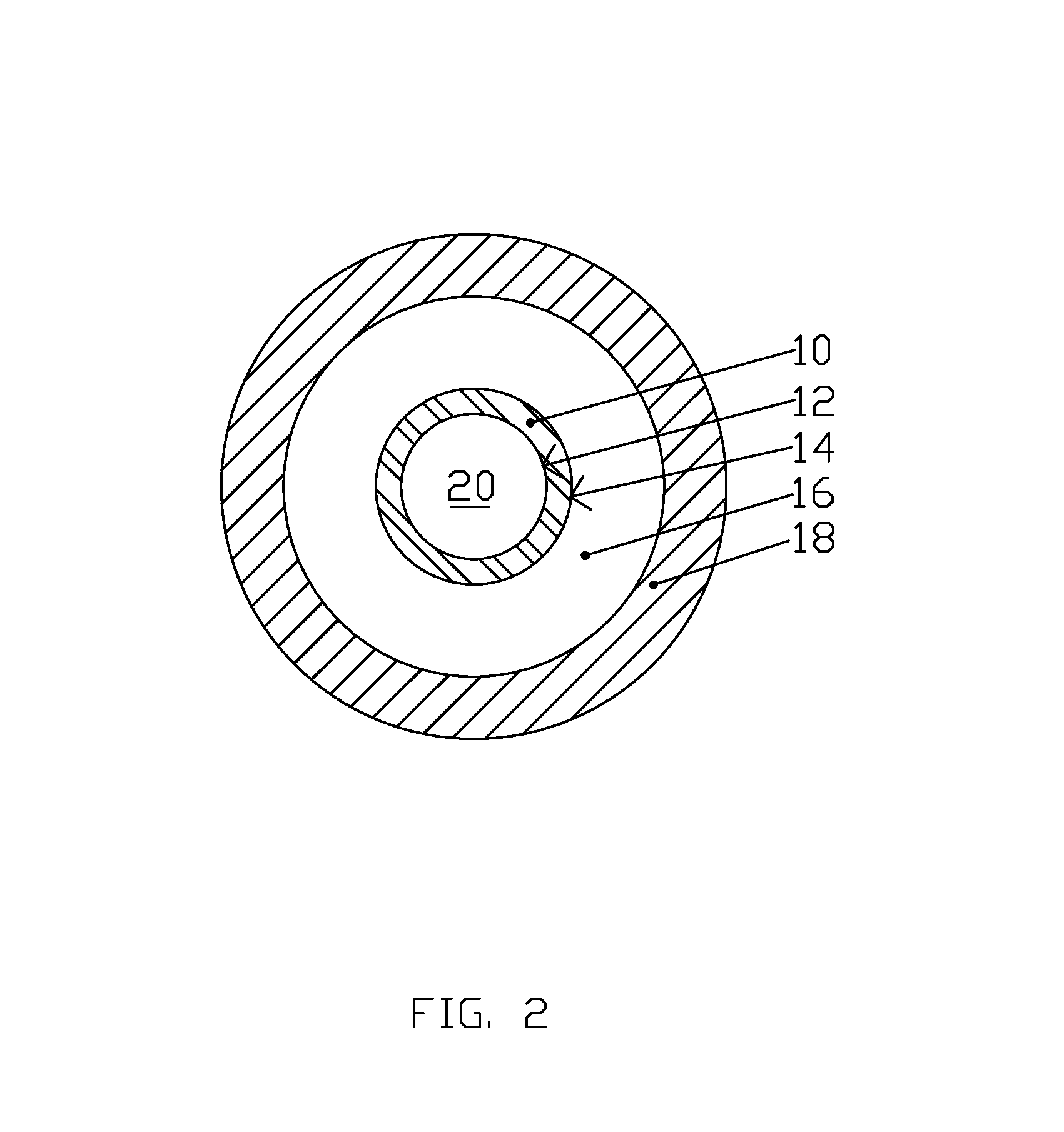

Image

  • Ceramic coating and process for applying the same
  • Ceramic coating and process for applying the same
  • Ceramic coating and process for applying the same

Examples


example 1

[0030]

GREEN SECONDWHITE FIRSTCERAMIC COMPOSITIONCERAMIC COMPOSITIONCERAMIC - (DILUTEDCERAMIC - (DILUTEDWITH WATER TOWITH WATER TOMAKE 5 GAL.)MAKE 5 GAL.)16 lb sodium silicate and20 lb sodium silicate andsilica crystallinesilica crystalline9 lb monoclinic zirconium10 lb monoclinic zirconium dioxide1 lb aluminum oxide5 lb aluminum oxide40 lb-50 lb potassium silicate40 lb-50 lb potassium silicate1 lb Silicon carbide3.5 lb Chromium Oxide green

example 2

[0031]

GREEN SECONDWHITE FIRSTCERAMIC COMPOSITIONCERAMIC COMPOSITIONCERAMIC - (DILUTEDCERAMIC - (DILUTEDWITH WATER TOWITH WATER TOMAKE 5 GAL.)MAKE 5 GAL.)16 lb sodium silicate and20 lb sodium silicate andsilica crystallinesilica crystalline9 lb monoclinic zirconium10 lb monoclinic zirconium dioxide1 lb aluminum oxide5 lb aluminum oxide1 lb Silicon carbide3.5 lb Chromium Oxide green

example 3

[0032]

GREEN SECONDWHITE FIRSTCERAMIC COMPOSITIONCERAMIC COMPOSITIONCERAMIC - (DILUTEDCERAMIC - (DILUTEDWITH WATER TOWITH WATER TOMAKE 5 GAL.)MAKE 5 GAL.)16 lb sodium silicate and20 lb sodium silicate andsilica crystallinesilica crystalline9 lb monoclinic zirconium4 lb monoclinic zirconium dioxide1 lb aluminum oxide4 lb aluminum oxide40 lb-50 lb potassium silicate2 lb dolomite1 lb Silicon carbide40-50 lb potassium silicate3.5 lb Chromium Oxide green


PUM

PropertyMeasurementUnit
temperatureaaaaaaaaaa
dew pointaaaaaaaaaa
thicknessaaaaaaaaaa

Abstract

A dual color sprayed on composite ceramic coating configured and formulated to protect fireside boiler tubing while also acting as a visual inspection aid. The coating is an environmentally safe, non-reactive, water soluble composite ceramic that will withstand operating temperatures up to 2000° F. (1093° C.). This coating is ideal for fluidized bed boilers and coal fired utility boilers experiencing tube erosion, corrosion and slagging. This sprayed-on ceramic coating system allows for fast application rates reducing equipment down time. The composite ceramic coating is a high solids system that will withstand severe thermal cycling from −300° F. (−185° C.) to 1600° F. (871° C.). This composite system is applied in two distinct colors to enable easy visual inspection of coating thickness.

Description

BACKGROUND OF THE INVENTION[0001]1. Field of the Invention[0002]This invention relates to a ceramic coating composition for use in boilers, furnaces, and the like, particularly for use on boiler tubes, and to a method for coating boiler tubes and other surfaces exposed to high temperatures to extend the service life and increase the thermal conductivity thereof, the coating being characterized by resistance to heat, erosion, corrosion, slagging, and fouling.[0003]2. Description of Related Art[0004]Boiler tubes generally have a relatively short life due to corrosion and erosion problems which exist in high temperature boilers. The high boiler temperatures together with the flow of hot gases carrying particles, soot and other wear and erosion-causing materials generally result in aggravated wear through the tube walls. Complete tube stacks or panels have been known to require replacement in a matter of months.[0005]In order to avoid or postpone the need to replace boiler tubes and oth...

Claims


Application Information

Patent Timeline
Patent Type & Authority Applications(United States)
IPC IPC(8): F22B37/06B05D7/00
CPCB05D7/52F22B37/06F22B37/107C23C24/04C23C28/042
Inventor LLOYD, EDWARD J.
Owner FIRESIDE COATINGS INC
Learn More