Light source device and image projection apparatus having light source device

a technology of light source device and image projection apparatus, which is applied in the direction of picture reproducers using projection devices, lighting and heating apparatus, instruments, etc., can solve the problems of reducing the safety of laser beams, and achieve the reduction of numerical aperture, low numerical aperture, and simple color composition

Active Publication Date: 2016-12-29
RICOH KK
View PDF21 Cites 11 Cited by
  • Summary
  • Abstract
  • Description
  • Claims
  • Application Information

AI Technical Summary

Benefits of technology

[0007]In addition, a design of an optical system can be easily achieved in the light source device using this kind of the solid light-emitting element, and the light source device has also advantageous effects that can achieve simplification of color composition, a low numerical aperture (low NA) of a projection lens (reduction of numerical aperture), etc.
[0008]However, when a laser light source is used for the light source device of the image projection apparatus, laser beam is coherent light having a regular wave front and has a high straightness. It is therefore preferable for the image projection apparatus to take a configuration in which laser does not directly enter person's eyes.
[0009]It is also preferable that laser beam of high energy strength does not hit a person's skin. Products having laser light sources are classified by the International Electrotechnical Commission (IEC60825) and the Japanese Industrial Standard (JIS C6802:2005), and the guidance that manufactures and users should be observed for each class is established. The guidance thereby contributes to the improvement in the safety of the products having the laser light sources.
[0010]In a light source device including the laser light source, in the image projection apparatus, a diffusion member relieving energy density of laser beam is provided in a traveling optical path of the laser beam such that laser beam with high output is not directly leaked to an exterior of the image projection apparatus to contribute to the improvement in the safety to the laser beam.
[0011]However, if the diffusion member deviates from the traveling optical path of the laser beam due to the falling etc. of the image projection apparatus, the laser beam is directly leaked to the exterior and therefore the safety to the laser beam is reduced. There is therefore proposed an image projection apparatus including a drive device that integrally rotates a fluorescent member and the diffusion member, and a light-shielding member engaged with the diffusion member, and configured to disengage the light-shielding member from the diffusion member when the diffusion member deviates from the traveling optical path of the laser beam, to move the light-shielding member at a position where the diffusion member exists by a centrifugal force, and to shield the laser beam, to prevent laser beam with high output from leaking to the exterior when the diffusion member deviates (see Paten Literature 1).
[0012]Moreover, Patent Literature 1 discloses a configuration including a detecting device detecting that the diffusion member deviates from the traveling optical path of the laser beam, or a detecting device detecting that the light-shielding member moves, and stopping the light emission from a laser light source.

Problems solved by technology

However, if the diffusion member deviates from the traveling optical path of the laser beam due to the falling etc. of the image projection apparatus, the laser beam is directly leaked to the exterior and therefore the safety to the laser beam is reduced.
However, anyway, the image projection apparatus disclosed in Patent Literature 1 presupposes that the diffusion member deviates from the traveling optical path of the laser beam and does not consider a case where a part of the diffusion member breaks even if the diffusion member does not deviate from the traveling optical path of the laser beam such that the diffusion member does not exist in the traveling optical path of the laser beam in a normal state.

Method used


Image

  • Light source device and image projection apparatus having light source device
  • Light source device and image projection apparatus having light source device
  • Light source device and image projection apparatus having light source device

Examples


embodiment 1

[0031]Embodiments of a light source device according to the present invention and an image projection apparatus including the light source device will be described hereinafter with reference to the accompanying drawings. FIGS. 1 to 6 are explanatory views of Embodiment 1 of the light source device according to the present invention.

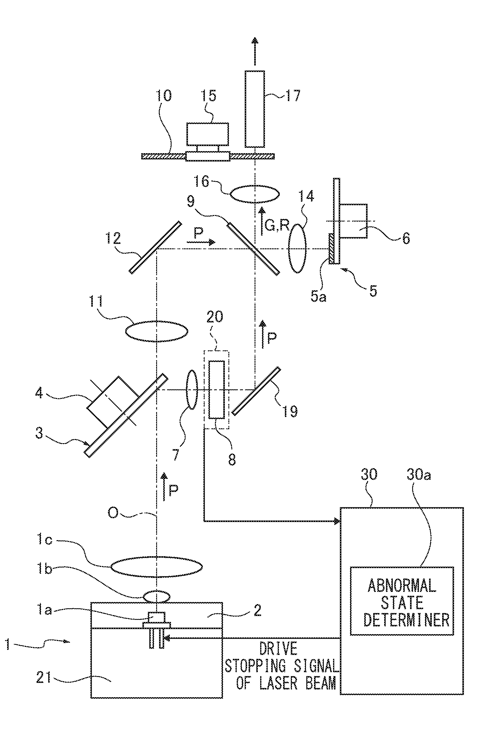
[0032]FIG. 1 is an optical view of the light source device according to the present invention. In FIG. 1, reference numeral 1 denotes a light source section. The light source section 1 includes a laser diode (LD) 1a as a laser light source, a coupling lens 1b, and a focusing lens 1c.

[0033]The laser diode 1a is provided on a laser diode holder 2. The coupling lens 1b is provided on a front surface of the laser diode holder 2 to face the laser diode 1a. Here, a heat sink (heat-releasing plate) 21 is provided on a rear surface of the laser diode holder 2 to cool heat generated in the laser diode 1a. The heat sink 21 is made of a metal such as aluminum or co...

embodiment 2

[0066]FIGS. 7 and 8 are explanatory views of Embodiment 2 of the light source device according to the present invention. In FIG. 7, identical reference numerals are attached to similar components to that shown FIG. 1 and detailed descriptions thereof are omitted. Only different components are described.

[0067]In Embodiment 2, a temperature detecting sensor (thermistor) 23 is used as the detection element. The temperature detecting sensor 23 is disposed in contact with the diffusion member 8 not to disturb transmission of the laser beam P.

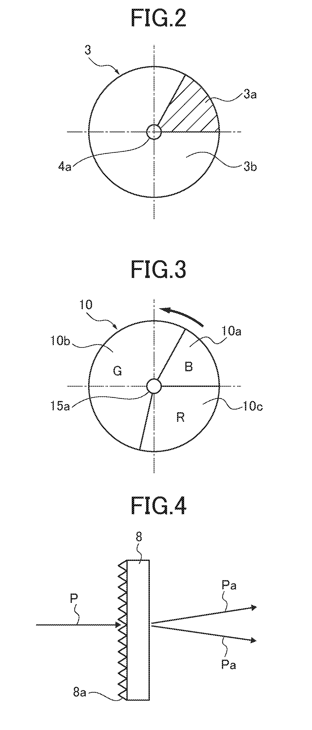
[0068]The diffusion member 8 may be a dielectric or may be not the dielectric, and has a physical characteristic in which a temperature is varied by radiation of the laser beam P. Transmissivity of the laser beam P to the diffusion member 8 is 97 to 98%, and 2 to 3% of the laser beam P is absorbed by the diffusion member 8 to be converted into heat energy.

[0069]The laser beam is converted in the heat energy when the laser beam P transmits the diffusi...

embodiment 3

[0074]FIGS. 9 and 10 are explanatory views of Embodiment 3 of the light source device according to the present invention. In FIG. 9, identical reference numerals are attached to similar components to that shown FIG. 1 and detailed descriptions thereof are omitted. Only different components are described.

[0075]In Embodiment 3, the diffusion member 8 is made of a light-transmitting member having magnetism. The diffusion member 8 is formed of a glass including highly-concentrated oxidation terbium. The diffusion member 8 maintains the light transmissivity and has a physical characteristic similar to that of a ferromagnetic body. A magnetic detection sensor 24 is used for the detection element. A hall element is used for the magnetic detection sensor 24, for example. The magnetic detection sensor 24 is disposed close to the diffusion member 8 not to disturb the transmission of the laser beam P.

[0076]The diffusion member 8 may be installed in a not-shown metallic frame. By installing the...


PUM


Abstract

A light source device includes a light source section that emits laser beam, a member reducing light quantity unevenness of the laser beam, a diffusion member that is provided in a traveling optical path of the laser beam between the light source section and the member reducing light quantity unevenness and diffuses the laser beam, a detection element that detects a physical characteristic of the diffusion member and outputs a state detecting signal, and an abnormal state determiner that determines an abnormal state of the diffusion member based on the state detecting signal.

Description

CROSS-REFERENCE TO RELATED APPLICATION[0001]The present application is a continuation application of International Application No. PCT / JP2014 / 077371 filed Oct. 15, 2014, the entire contents of which are hereby incorporated herein by reference, which claims priority to Japanese priority application No. 2014-55347, filed on Mar. 18, 2014.TECHNICAL FIELD[0002]The present invention relates to a light source device and an image projection apparatus including the light source device.BACKGROUND ART[0003]An image projection apparatus (projector) that projects an image on a screen (viewing surface) by using image data of a personal computer, data of a video image, image data stored in a memory card, etc. is known today.[0004]The image projection apparatus (projector) projects light emitted from a light source device on the screen by using a micro mirror displaying element which is used as a micro mirror device, a liquid crystal plate, or the like, and forms an image on the screen.[0005]A hig...

Claims


Application Information

Patent Timeline
Patent Type & Authority Applications(United States)
IPC IPC(8): G03B21/20H04N9/31F21V23/00F21V3/00F21V9/16
CPCG03B21/2086G03B21/2033G03B21/208H04N9/3161G03B21/204F21V9/16F21V23/003F21V3/00F21V13/14F21V9/30G02B5/0278H04N9/3114H04N9/3158G02B5/02
Inventor NISHIMORI, TAKEHIROFUJITA, KAZUHIROMURAI, TOSHIHARUTAKAHASHI, TATSUYA
Owner RICOH KK
Why Eureka
Try Eureka