Device and method for controlling chemical injection into boiler

a technology of chemical injection and boiler, which is applied in the direction of treatment control/steering, lighting and heating apparatus, corrosion-reducing boiler components, etc., can solve the problems of pump deformation, pump failure, and variable flow rate of feed-water, so as to prevent the occurrence of scale, prevent the effect of scale and proper blowing control

Inactive Publication Date: 2017-01-12
KURITA WATER INDUSTRIES LTD
View PDF8 Cites 8 Cited by
  • Summary
  • Abstract
  • Description
  • Claims
  • Application Information

AI Technical Summary

Benefits of technology

[0033]In the first and second inventions, the chemical injection pump is proportionally-controlled in accordance with the measured value of the feed-water flow rate in a basic mode. At a time when a predetermined period, i.e., a predetermined time, has lapsed, or when an integrated value of the feed-water flow rate reaches a predetermined value, an average chemical concentration in the feed-water during the predetermined period is calculated. The average chemical concentration is determined from the chemical liquid reduction amount in the chemical tank and the integrated value of the feed-water flow rate.
[0034]The calculated chemical concentration is determined whether it is within the preset target concentration range. When the calculated chemical concentration is outside the range, the injection amount (dosage) is corrected such that a target value is satisfied. For example, the injection amount is controlled by multiplying an output signal of the feed-water flowmeter by a proportionality coefficient, and applying a resultant signal to the chemical injection pump.
[0035]Thus, the real-time proportional control of the chemical injection pump relative to the feed-water flow rate is combined with the feedback control of checking the actual average target concentration during the predetermined period and finely adjusting the chemical amount injected by the chemical injection pump. Therefore, even in a system in which the flow rate varies to a large extent in a short period as in a feed-water pipe provided with a plurality of small once-through boilers, the chemical concentration in the feed-water can be stably maintained within the target range. According to the present invention, even when the injection amount deviates from the target value due to, e.g., degradation of the performance of the chemical

Problems solved by technology

In the case where a plurality of small once-through boilers are installed and operated, feed-water pumps for the individual boilers irregularly operate and cause variations in flow rates of feed-water.
In the case of supplying the feed-water by merely controlling the chemical injection pump in accordance with the pulse signal or the analog signal from the feed-water flowmeter, an error between an actual injection amount and a target injection amount increases when the performance of the feed-water pump or the chemical injection pump degrades.
If the chemical concentration in the feed-water is lower than the target concentration, there arise problems, for example, that the effect of an anticorrosive becomes insufficient in equipment (such as a feed-water pipe and an economizer) prior to reaching a boiler drum, and that the deoxidization effect of a deoxidizer reduces.
Conversely, if chemicals are added in excess, it is uneconomical.
Hence the proposed method has a problem that, in a facility causing large variations in the flow rate as in a feed-water facility equipped with a plurality of small once-through boilers, a control signal varies to a large extent depending on the timing of detection by the flowmeter, time lags in calculation and control, etc., and a difficulty occurs in keeping the injection amount appropriate.
In some cases, however, a particular component becomes deficient or excessive for the reason that the quality or the temperature of feed-water varies due to variations in drain recovery or quality of raw water, and that balance among the required amounts of an alkali aid, a deoxidizer, an anticorrosive, a dispersant, etc. varies.
When the latter method is applied to a boiler in which a degree of concentration is controlled by discharging blow water upon the electrical conductivity of the boiler water reaching a setting upper limit value, and by stopping the discharge of the blow water upon

Method used


Image

  • Device and method for controlling chemical injection into boiler
  • Device and method for controlling chemical injection into boiler
  • Device and method for controlling chemical injection into boiler

Examples


example 1-1

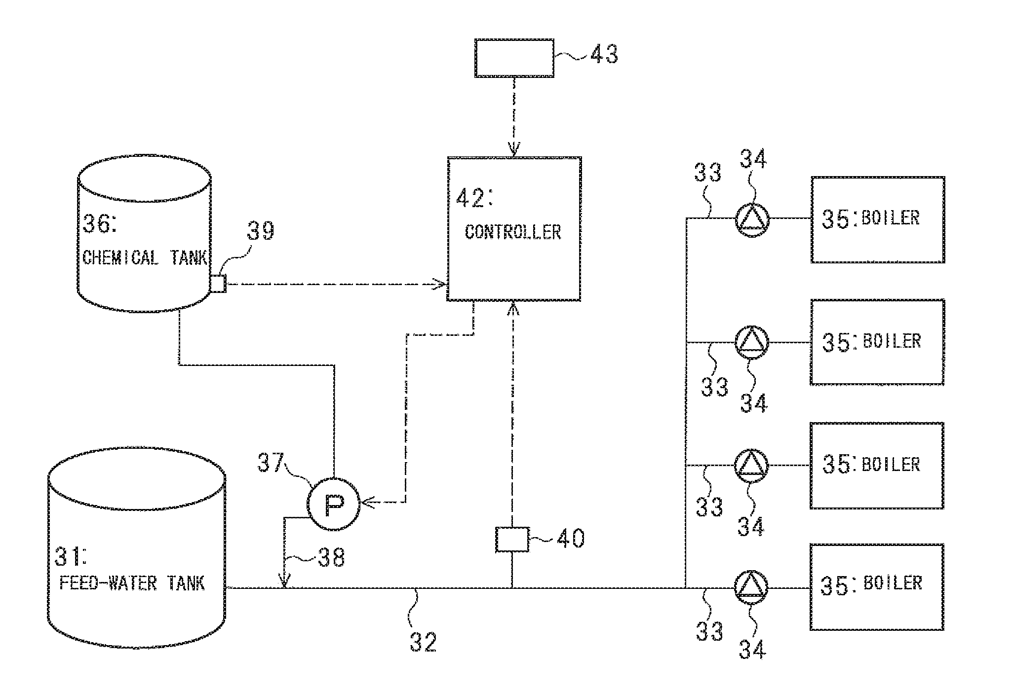
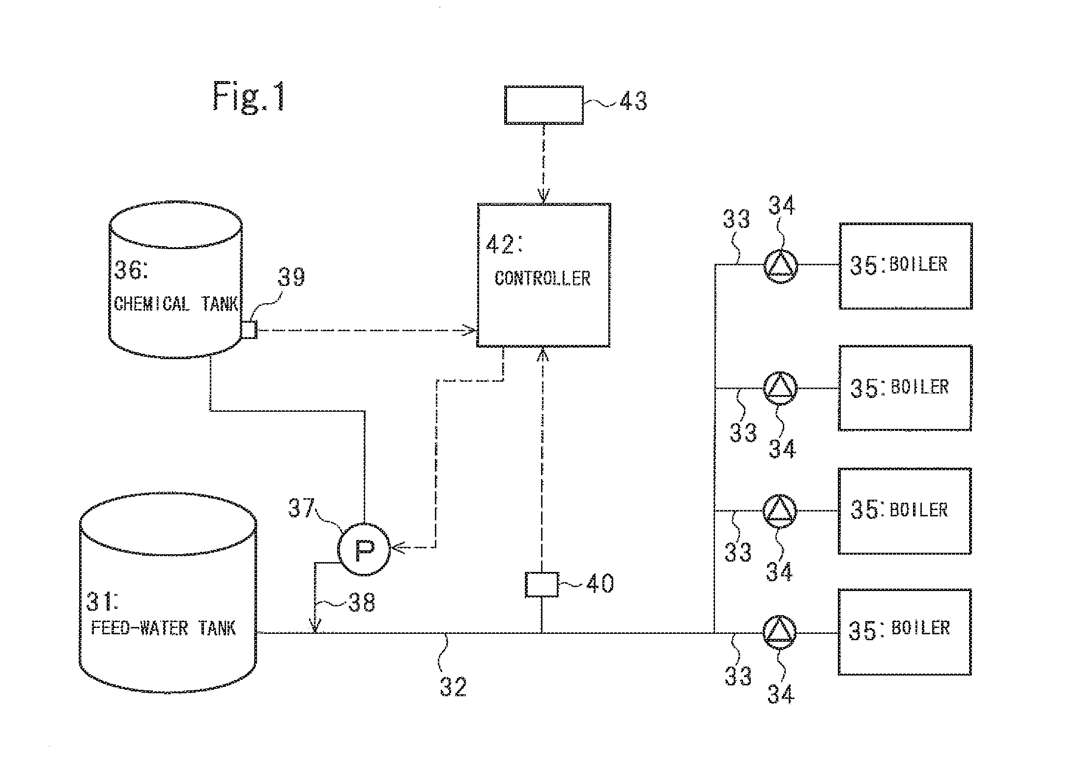
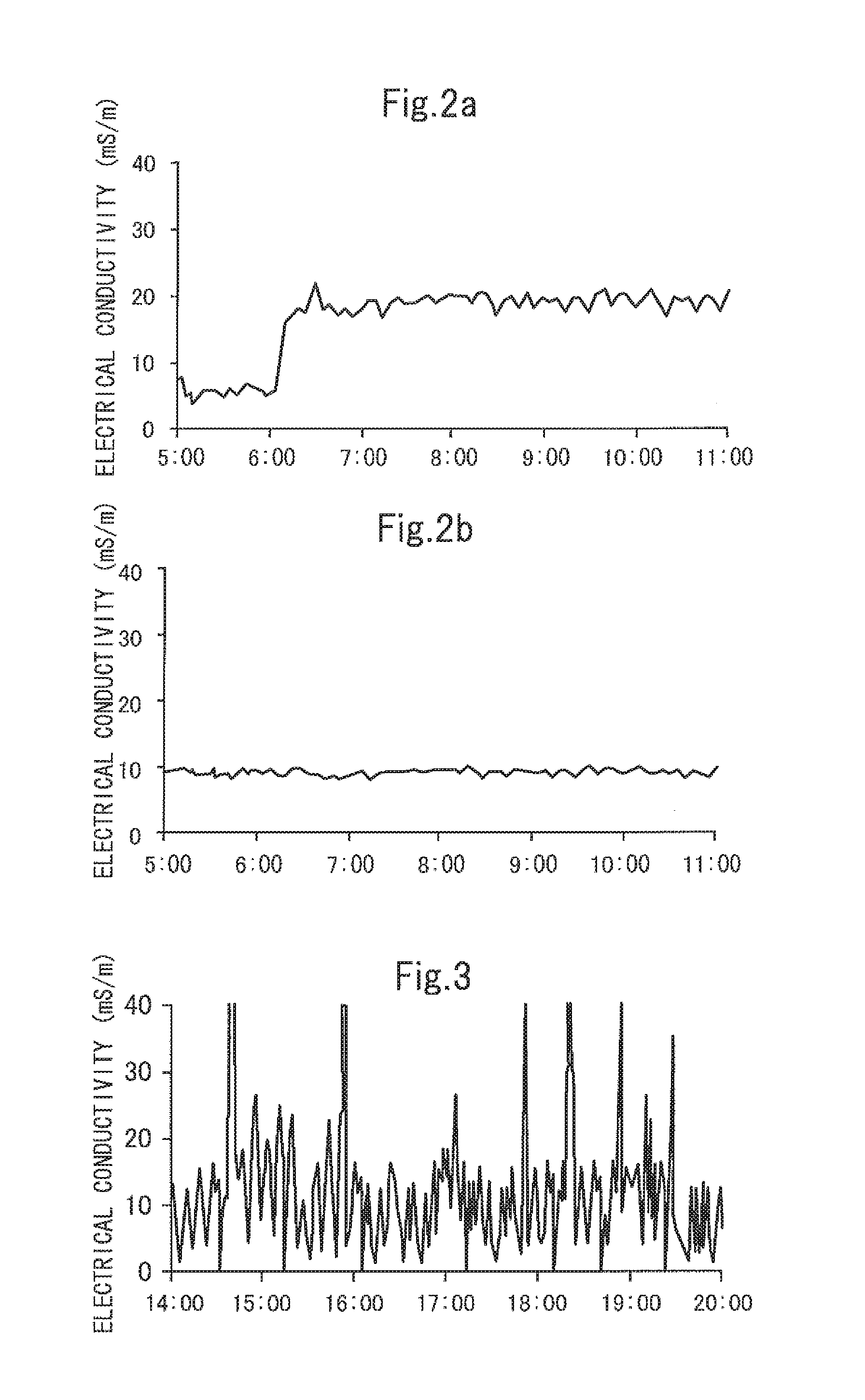
[0073]Under control according to the method of the present invention, the chemical liquid was injected into the feed-water main pipe 32 in the facility, illustrated in FIG. 1 on condition that the target chemical concentration in the feed-water was 100 mg / L. The facility was equipped with four small once-through boilers (NBO-500N made by SAMSON CO., LTD.). In order to check proper development of the chemical injection control function, the facility was operated in a manner of setting the number of pump strokes at startup of the operation so as to provide the chemical concentration of 50 mg / L, and obtaining the chemical concentration of 100 mg / L after 1 hour from the startup of the operation with the correction under the feedback control through calculation of the chemical concentration. A chemical injection point was set to a position away from an outlet of the feed-water tank through a distance of 500 mm. The chemical liquid was injected in a state that the nozzle 38 made of SUS an...

examples 1-2 and 1-3

[0087]In order to check proper development of the function of automatically correcting the injection amount when the performance of the chemical injection pump or the feed-water pump degraded, the chemical injection was performed in accordance with the method of the present invention under a condition modified from among the conditions of EXAMPLE 1-1 in that the stroke length of the chemical injection pump was changed from 100% to 50% (EXAMPLE 1-2), and that the opening degree of an outlet valve of the feed-water pump was reduced to half (EXAMPLE 1-3). The obtained results are indicated in FIGS. 5 and 6 and Tables 2 and 3.

TABLE 2Results of checking function of automatically correctinginjection amount with method of present inventionTiming Interval for Measuring Injection Amount~(1)(1)~(2)(2)~(3)(3)~(4)(4)~(5)(5)~(6)Stroke of Chemical100%100%100%→50%50%50%50%Injection PumpInjection Amount101995681102102(mg / L)Average Electrical19.018.710.515.219.219.1Conductivity (mS / m)

TABLE 3Results ...

embodiment

of Third and Fourth Inventions

[0091]An embodiment of third and fourth inventions will be described below with reference to FIG. 7. FIG. 7 is a block diagram of a boiler feed-water facility equipped with a device for controlling chemical injection into a boiler according to the embodiment. Feed-water in a feed-water tank 1 is supplied to individual boilers 5 through a feed-water main pipe 2, a plurality of feed-water branch pipes 3 branched from the feed-water main pipe 2, and feed-water pumps 4 disposed respectively in the feed-water branch pipes 3. A chemical liquid, i.e., a solution containing one or more chemicals for boiler water treatment, is stored in a chemical tank 6, and the chemical liquid is injected into the feed-water main pipe 2 through a chemical injection pump 7 and a chemical injection nozzle 8.

[0092]The chemical tank 6 is provided with a chemical liquid amount sensor 9 for measuring an amount of the chemical liquid. The feed-water main pipe 2 is provided with a flo...


PUM


Abstract

A device for controlling injection of chemical into a boiler and a chemical injection method can control an injection amount such that a chemical concentration is obtained as per a target even in a boiler feed-water facility where a flow rate of feed-water varies to a large extent in a short period. The device controls an amount discharged by a chemical injection pump in proportion to a flow rate measured by a flowmeter. An average chemical concentration in a feed-water is calculated from an amount of feed-water per predetermined period obtained by the flowmeter and a reduction in the amount of chemical in a tank per predetermined period obtained by a sensor. The chemical injection pump is controlled on the basis of the calculated average chemical concentration and a preset target chemical concentration of the feed-water so that the average chemical concentration is within the target chemical concentration range.

Description

FIELD OF INVENTION[0001]The present invention relates to a device and a method for controlling chemical injection into a boiler, and more particularly to a chemical injection control device and method, which are suitable to inject a chemical liquid into a feed-water line provided with a plurality of small once-through boilers.BACKGROUND OF INVENTION[0002]A feed-water pump for a small once-through boiler is usually controlled to start an operation when a boiler water level reduces down to a setting lower limit value or below, and to stop the operation when the boiler water level reaches a setting upper limit value. Accordingly, the feed-water pump irregularly operates and causes variations in a flow rate of feed-water depending on a combustion state of the boiler. In the case where a plurality of small once-through boilers are installed and operated, feed-water pumps for the individual boilers irregularly operate and cause variations in flow rates of feed-water. Therefore, a flow rat...

Claims


Application Information

Patent Timeline
IPC IPC(8): C02F1/68F22B37/02C02F1/00
CPCC02F1/686C02F1/008F22B37/025C02F2209/02C02F2209/40C02F2209/05C02F2209/006C02F2209/005
Inventor SHIMPO, CHIKAKOSHIMURA, YUKIMASA
Owner KURITA WATER INDUSTRIES LTD
Why Eureka
Try Eureka