Sensible Thermal Energy Storage (STES) Systems

a technology of thermal energy storage and sensing, applied in the field of sensing thermal energy storage (stes) systems, can solve the problems of inability to use, inability to meet the needs of solar salt, etc., to achieve the effect of high heat storage and recovery efficiency, and reducing the total storage volum

Active Publication Date: 2017-03-09
CHOI PETER B
View PDF7 Cites 19 Cited by
  • Summary
  • Abstract
  • Description
  • Claims
  • Application Information

AI Technical Summary

Benefits of technology

[0031]The multi-chamber STES system in a sequence operation yields the high heat storage and recovery efficiencies because no streams at different temperatures are mixed during the heat transfer operation. Such operation also requires about a half of the total storage volume as compared with that of the two tank system of the solar salt operating at the power tower receiver exit temperature of 565° C. For example, a multi-chamber system having six chambers with one chamber of them provided as an empty one in a sequence operation can reduce the total storage volume by 40% when compared with the two tank system. This multi-chamber STES system is also more practical and efficient than the thermocline tank system or the single tank system that has a horizontally floating partition panel; they have not been successful for commercial application where the maximum storage temperature is 565° C.
[0032]The multi-chamber system with a molten carbonate liquid used as a HTF in this embodiment is operating by a system controller such that an empty chamber is made available among a plurality of chambers, when the multi-chamber system is charged or discharged. In the daytime, for example, when a thermally discharged chamber is being charged, a cold liquid at 600° C. is withdrawn from the discharged chamber, heated by a power tower receiver to 800° C., and returns to the empty chamber. When the empty chamber is filled completely with the hot liquid at 800° C., the current discharged chamber where the cold liquid has been withdrawn becomes empty at the end of the cold liquid withdrawing step and starts to receive the hot liquid from the power tower receiver that originated from the next discharged chamber at 600° C. Such sequence operation continues while all chambers in the multi-chamber system except an empty chamber are completely charged with the hot liquid at 800° C. during the daytime. In the nighttime when the thermally charged chamber is discharging, a hot liquid at 800° C. is withdrawn from the charged chamber, cooled in a heat recovery exchanger to 600° C., and returns to the empty chamber. When the empty chamber is filled completely with the cold liquid at 600° C., the current charged chamber where the hot liquid has been withdrawn becomes empty at the end of the hot liquid withdrawing step and starts to receive the cold liquid from the heat recovery exchanger that originated from the next charged chamber at 800° C. Such sequence operation continues while all chambers in the multi-chamber system except an empty chamber are fully discharged during the nighttime. This sequence operation ensures that no mixing of streams at different temperatures takes place and that very high heat storage and recovery efficiencies can be achieved with a minimum loss of the available work.
[0033]With an empty chamber being made available to receive a hot or a cold stream originating from another chamber among a plurality of chambers, the total volume of the multi-chamber STES system can be reduced to almost a half of the combined volume of the hot and cold storage tanks in the solar salt TES system. Since, at the high service temperatures around 800° C., the tensile strength of the metal plates becomes significantly lower, it forces to build multiple small tanks instead of a single large tank such as the one having a diameter of 40 meters. The reduction of the total STES volume by about a half in this invention compared with the two tank storage system of the solar salt is a great advantage in the effort by the solar utility industry to lower the cost for electricity generation from the solar energy below the current price of $0.07 per KWH from the fossil fuels.

Problems solved by technology

%) has been mainly used as a thermal energy storage (TES) medium for the parabolic trough collectors with a synthetic oil employed as a heat transfer fluid (HTF) at temperatures up to 400° C. For the power tower, the solar salt is used as a TES medium as well as a HTF up to 565° C. For thermal energy above 565° C., the solar salt is not suitable for the service, because it becomes thermally unstable above this temperature.
This synthetic oil can be used only up to 400° C., however, because it becomes thermally unstable above this temperature.
The solar salt, however, becomes thermally unstable from around 565° C., and cannot be used above this temperature.
The candidates for the new TES medium include the eutectic mixtures of carbonate, chloride, and fluoride alkali metal compounds that can be used between 565° C. and 850° C. Unlike the solar salt, they are very corrosive making it more costly to employ the process equipment units constructed of high nickel alloys that are compatible with the molten salt liquids.
Also, the carbonate salts are thermally unstable at the service temperatures.
As a liquid HTF, molten metal or metal salts such as Na, Pb and NaK have been used as a HTF, but have low specific heat making it difficult to be used as a TES medium at the same time.
Na and NaK are also very flammable when spilled, so the safety is a major concern.
This need makes the fluoride salts too expensive to be used for CSP plants.
The gases have very low heat capacities, and cannot provide a cushion even for the disturbances from the heat sources such as those caused by clouds in solar irradiation.
The gaseous HTF's, however, usually require very high volumetric flow rates at moderate pressures due to their low volumetric specific heat capacity limiting their use.
At the present time, there is no reliable TES system available for the commercial CSP plants at service temperatures above 565° C. the highest temperature at which the molten solar salt can be used.

Method used


Image

  • Sensible Thermal Energy Storage (STES) Systems
  • Sensible Thermal Energy Storage (STES) Systems
  • Sensible Thermal Energy Storage (STES) Systems

Examples


first embodiment

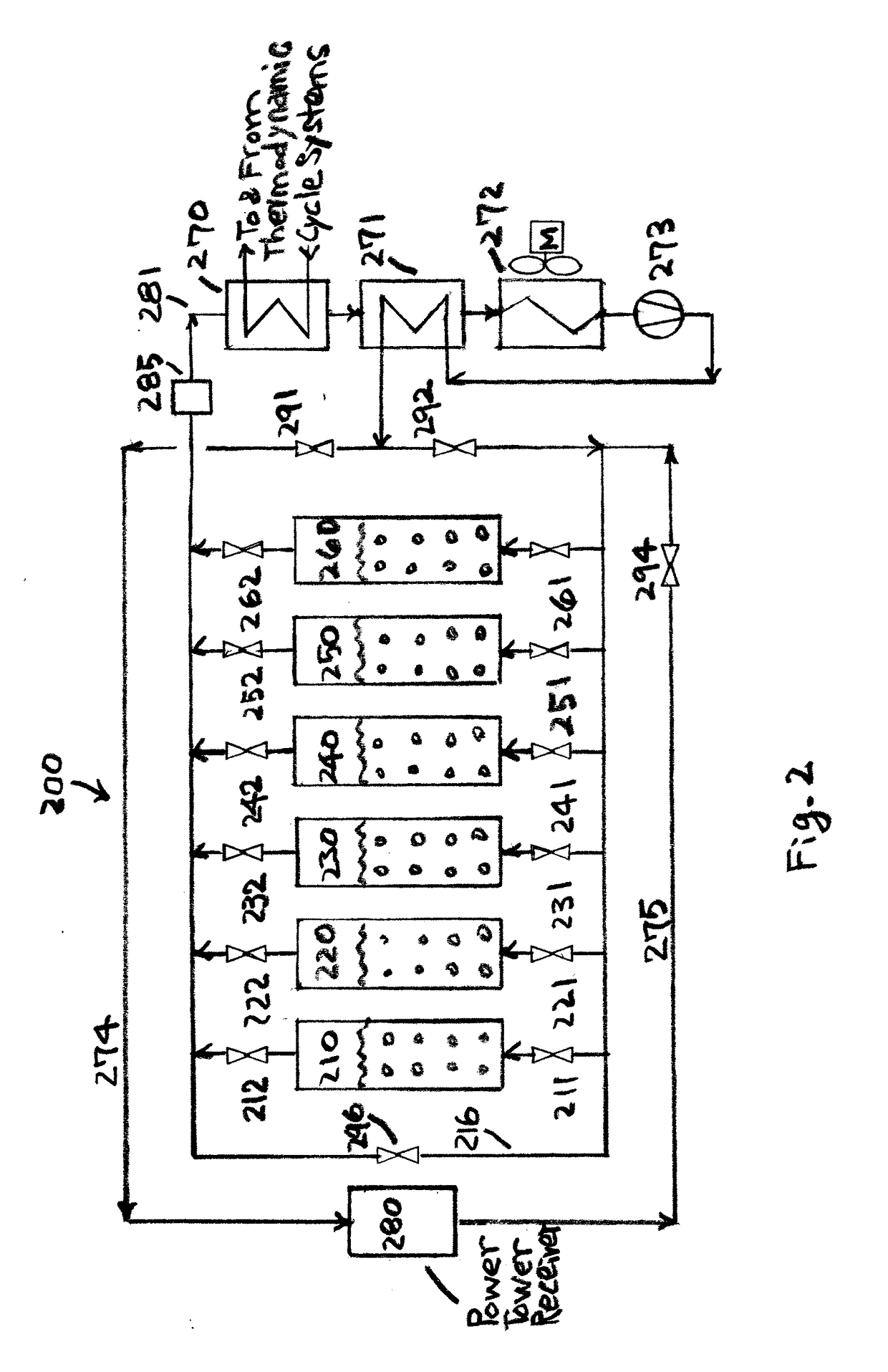
[0051]this invention in FIG. 2 shows a multi-chamber STES system for charging and discharging thermal energy from a power tower receiver using an immiscible gaseous HTF. The system converts a form of thermal energy of low volumetric heat capacity at temperatures near 900° C. to a form of dispatchable energy of high volumetric heat capacity at temperatures above 600° C. For this purpose, the process uses a gaseous HTF that is heated up to a temperature around 900° C. by a power tower receiver, and contacted by gas bubbling with the molten eutectic salt layer to store the thermal energy at 800° C. at an optimum system operating pressure. While the individual chambers are cooled from 800° C. to 600° C. in the heat discharging steps, the multi-chamber system as a whole generates an output gas stream at a constant temperature of 700° C. In practice, the operating pressure and temperature for the system are determined by a trade-off analysis.

[0052]Circulating gaseous HTF stream 274 must b...

second embodiment

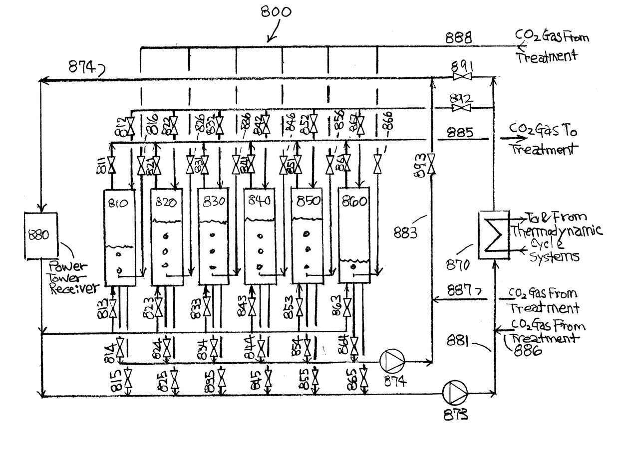
[0086]For this invention, a multi-chamber STES system with a molten eutectic salt liquid being used as a TES medium and also as a liquid HTF is illustrated in FIG. 6. The system is utilized for charging and discharging thermal energy from power tower 680. System 600 comprises chambers 610, 620, 630, 640, 650 and 660, heat recovery exchanger 670, power tower receiver 680, heat recovery pump 673, and heat storage pump 674.

[0087]During the daytime, system 600 supplies thermal energy to the thermodynamic cycle systems for generation of electricity and also charges heat to the TES chambers. At this time, valves 644, 691 and 693 are opened and valve 692 is closed. Two pumps 673 and 674 work simultaneously; pump 673 for electricity generation and pump 674 for heat storage. Pump 673 circulates the molten salt liquid through heat recovery exchanger 670, and pump 674 from one of the chambers containing cold liquid, for example, from chamber 610 by opening valves 611 and 614 and closing valves...


PUM

PropertyMeasurementUnit
temperaturesaaaaaaaaaa
temperatureaaaaaaaaaa

Abstract

Two sensible thermal energy storage (STES) systems in multiple chambers containing molten eutectic salts have been devised for use at temperatures above 565° C. For the first type, the thermal energy of low specific heat of an immiscible gaseous heat transfer fluid (HTF) at temperatures above 900° C. is readily converted to dispatchable heat of high specific heat in the molten eutectic salt liquid layers operating at high temperatures, which can again produce a gaseous HTF at a constant temperature of 700° C. or higher for the lower electricity generation capacities. For the second type, the molten eutectic salt liquids are used as a thermal energy storage (TES) medium and also a HTF at temperatures above 700° C. for the higher electricity generation capacities. These STES systems provide an effective cushion against the disturbances of heat supply from the sun.

Description

CROSS-REFERENCE TO RELATED APPLICATION[0001]This application claims priority to U.S. Provisional Application No. 62 / 215,207, filed on Sep. 8, 2015.FIELD OF INVENTION[0002]The present invention is related to the storage and the release of thermal energy in the sensible thermal energy storage (STES) containing molten eutectic salt liquids at temperatures above 565° C., the stored thermal energy being used for generation of electricity in the night.BACKGROUND OF THE INVENTION[0003]In the commercial concentrated solar power (CSP) applications, sensible thermal energy storage (STES) for the high temperature solar collectors is available for temperatures up to 565° C. For example, the solar salt a binary eutectic mixture of KNO3 (54 wt. %) and NaNO3 (46 wt. %) has been mainly used as a thermal energy storage (TES) medium for the parabolic trough collectors with a synthetic oil employed as a heat transfer fluid (HTF) at temperatures up to 400° C. For the power tower, the solar salt is used...

Claims


Application Information

Patent Timeline
Patent Type & Authority Applications(United States)
IPC IPC(8): F24J2/34
CPCF24J2/34F03G6/068F24S20/20F24S60/10F24S80/20F28D20/0034F28D2020/0047Y02E10/46Y02E60/14Y02E10/40
Inventor CHOI, PETER B.
Owner CHOI PETER B
Why Eureka
Try Eureka