Corrosion control for chamber components

a technology of corrosion control and chamber components, applied in the direction of spindle sealing, mechanical equipment, coatings, etc., can solve the problems of process contamination and process skew

Active Publication Date: 2017-06-01
APPLIED MATERIALS INC
View PDF5 Cites 213 Cited by
  • Summary
  • Abstract
  • Description
  • Claims
  • Application Information

AI Technical Summary

Benefits of technology

[0008]Implementations described herein protect a chamber components from corrosive cleaning gases used at high temperatures. In one embodiment, a chamber component in a form of a bellows is provided that includes a top mounting flange coupled to a bottom mounting flange by a tubular accordion structure. A coating is disposed on an exterior surface of at least the tubular accordion structure. The coating includes of at least one of polytetrafluoroethylene (PTFE), parylene C, parylene D, diamond-like carbon, yttria stabilized zirconia, alumina, or aluminum silicon magnesium yttrium oxygen compound.

Problems solved by technology

However, during continuous operation of the processing chamber, the corrosive agents in the chamber attack the chamber components and generate residual particles which increase the concentration of chromium, titanium and molybdenum in the interior volume of the processes chamber.
The stray materials in the deposition environment may eventually find its way into the films deposited on the substrate and undesirably contribute to process contamination and process skew.

Method used


Image

  • Corrosion control for chamber components
  • Corrosion control for chamber components
  • Corrosion control for chamber components

Examples


first embodiment

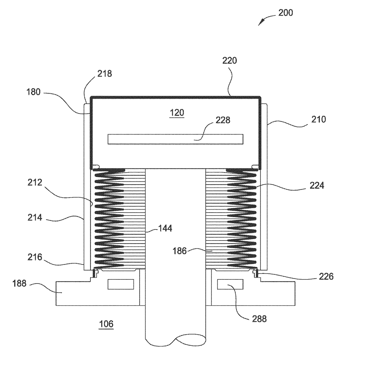
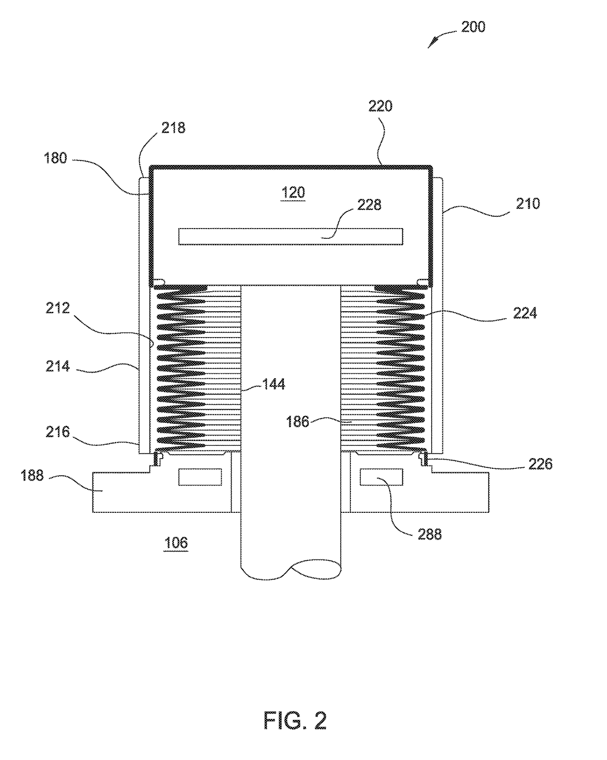
[0042]In a first embodiment, the coating 180 and the shield 210 are used to protect the substrate support 120, the flange 188, and bellows 186. The substrate support 120 and bellows 186 may be formed from nickel-chromium alloy. The shield 210 may be formed from aluminum, such as 6061-T6. The coating 180 may be formed from a polytetrafluoroethylene (PTFE), or parylene C or D material. The coating 180 may be from about 0.5 microns to about 50.0 microns, such as about 5 microns. The polytetrafluoroethylene (PTFE), or parylene C or D material may be chemical vapor deposited to form multiple layers, and may optionally have a bonding layer disposed therebetween. The coating 180 may be a very thin and conformal top layer, and for example, may be deposited using physical vapor deposition and / or chemical vapor deposition. The coating 180 is formed on the substrate support 120 and the bellows 186. The coating 180 on the substrate support 120 may be continuous and extend to and cover the bello...

second embodiment

[0043]In a second embodiment, the coating 224 on the bellows 186 is formed from a diamond-like carbon or a ceramic material such as yttria stabilized zirconia or alumina or AsMy. The coating 224 may have a thickness of about 0.5 microns to about 50.0 microns, such as about 5 microns for DLC and about 25 microns for ceramic. The diamond-like carbon or ceramic material may be chemical vapor deposited with multilayers having a bonding layer in between. A very thin and conformal top layer may be deposited using physical vapor deposition or chemical vapor deposition to cover any pours. The coating 220 of the substrate support 120 may be formed from polytetrafluoroethylene (PTFE), or parylene C or D, the diamond-like carbon or a ceramic material or a metal, such as a nickel coating. The coating 220 may have a thickness of about 0.5 microns to about 50.0 microns, such as about 12 microns. The coating 220 may be plasma sprayed with multilayers having a bonding layer in between and a thin co...

third embodiment

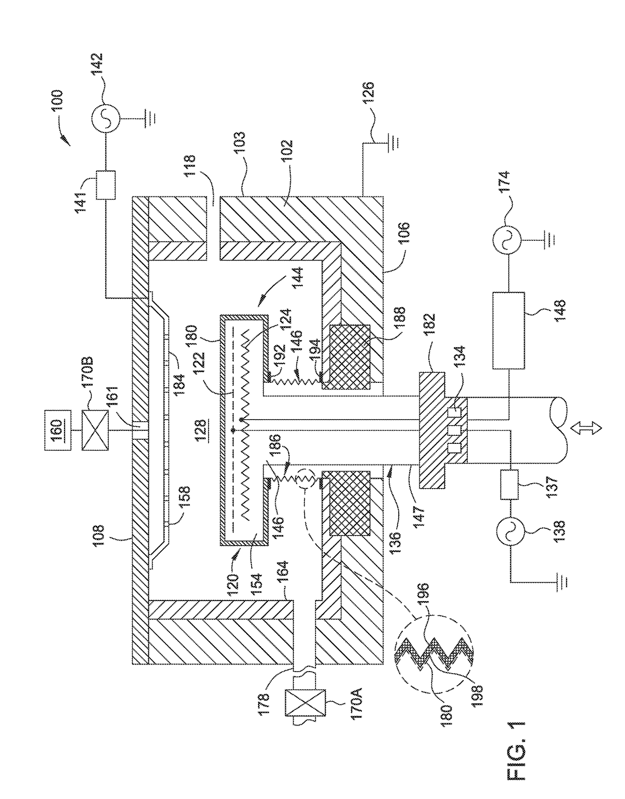
[0044]In a third embodiment, the bellows 186 are formed from Inconel 625 and protected from the corrosive processing gases and high temperatures by a flexible shield 310. FIG. 3 illustrates a side plan view of another substrate support assembly 300 for use in the plasma processing chamber 100. The substrate support assembly 300 has the flexible shield 310 for corrosion protection of the bellows 186. The flexible shield 310 may be made from polytetrafluoroethylene (PTFE) or other suitable material. The flexible shield 310 may have a snap seal 312 at one end and a second snap seal 314 at a second end. The substrate support 120 may have a feature 322 for interfacing with the snap seal 312. Additionally, a second feature 384 may be disposed on the flange188 for interfacing with the second snap seal 314. The snap seals 312, 314 and features 322, 384 may be in the form of a male / female interface, ball and socket, or other two part fastening system for sealingly joining to components. The ...


PUM

PropertyMeasurementUnit
thicknessaaaaaaaaaa
thicknessaaaaaaaaaa
diameteraaaaaaaaaa

Abstract

Implementations described herein protect a chamber components from corrosive cleaning gases used at high temperatures. In one embodiment, a chamber component includes at least a bellows that includes a top mounting flange coupled to a bottom mounting flange by a tubular accordion structure. A coating is disposed on an exterior surface of at least the tubular accordion structure. The coating includes of at least one of polytetrafluoroethylene, parylene C, parylene D, diamond-like carbon (DLC), yttria stabilized zirconia, nickel, alumina, or aluminum silicon magnesium yttrium oxygen compound. In one embodiment, the chamber component is a valve having an internal bellows.

Description

BACKGROUND[0001]Field[0002]Implementations described herein generally relate to semiconductor manufacturing and more particularly to a chamber components for protecting vacuum processing equipment from corrosion.[0003]Description of the Related Art[0004]During the manufacture of semiconductor devices, a substrate may undergo many operations in a variety of processing chambers for the purpose of forming material layers and features suitable for an end use. For example, the substrate may undergo several depositions, annealing, and etching operations, among other operations. The process chambers are formed from a variety of components formed from aluminum containing compounds, steel containing compounds, nickel containing compounds, among other compounds. These compounds may additionally contain chromium, titanium and molybdenum among other materials.[0005]Device miniaturization has made small dimensions for device patterns formed in a film layer of the substrate more critical. Achievi...

Claims


Application Information

Patent Timeline
Patent Type & Authority Applications(United States)
IPC IPC(8): F16K41/10H01J37/32F16L11/15H01L21/687
CPCF16K41/10H01L21/68757F16L11/15H01J37/32477H01J37/32495H01L21/68792C23C16/4404
Inventor RAJ, GOVINDAKUMAR, HANISHZHANG, LINWU, STANLEY
Owner APPLIED MATERIALS INC
Why Eureka
Try Eureka