Nanostructured Coated Substrates for Use in Cutting Tool Applications

Active Publication Date: 2017-06-15
P&S GLOBAL HLDG LLC
View PDF7 Cites 3 Cited by
  • Summary
  • Abstract
  • Description
  • Claims
  • Application Information

AI Technical Summary

Benefits of technology

The present invention is about a coating that can be applied to a substrate to enhance its wear resistance. The coating is made up of a nanostructured layer of functional particles that can be deposited as a single layer or multiple layers. The coating can also include additional layers such as non-nanostructured layers and a capping layer. The coating can be produced using high-temperature chemical vapor deposition techniques, which are different from traditional low-temperature physical vapor deposition techniques. The coating can be pre-treated and post-treated to further improve its wear resistance. The nanostructured coating has improved hardness and toughness, which reduces edge chip-off and flank wear in difficult applications such as machining hardened steel with interruptions or machining of heat-resistant alloys. The non-nanostructured layer acts as a thermal barrier.

Problems solved by technology

Wear on the coatings of cutting tool inserts is a well-recognized problem, particularly in connection with certain difficult cutting applications.
Coatings applied to carbide substrates produced using chemical vapor deposition (CVD) processes, a common technique, may be chipped off, resulting in premature failure of the cutting tool insert, or exhibit excessive flank wear, again leading to poor performance for the cutting tool insert.
Another application that presents significant challenges is the machining of heat-resistant alloys.
Such applications impose challenges including excessive heat generation at the tool-workpiece interface, workpiece hardening, and expedited tool wear including notch wear.
Because of these challenges, machining of heat resistant alloys has generally been limited to relatively low material removal rate (i.e. low surface speed and feed rate).
Advances including tool material formulation development, chip breaker design, edge honing, and coating formulation have been made to address these challenges, but problems still remain.
However, the up sharp edge tends to chip or break due to unstable machining settings, including machine setup rigidity, interruptions, or out-of-roundness on workpieces.
The chipped edge, in turn, increases cutting forces and therefore increases heat.
This causes further degradation of workpiece surface finishes.
While this provides the necessary edge protection, it typically results in significant heat generation, which further degrades workpiece surface finishes.

Method used


Image

  • Nanostructured Coated Substrates for Use in Cutting Tool Applications
  • Nanostructured Coated Substrates for Use in Cutting Tool Applications
  • Nanostructured Coated Substrates for Use in Cutting Tool Applications

Examples


example 1

[0046]In this case study, two cutting tool inserts were compared using semi-finish OD turning of rings of Inconel 718 alloys. The first insert was an RPGN-3V carbide grade (C2) substrate with up sharp edge in uncoated form. The second insert was a RPGN-3V carbide insert with a multiple-layer nanostructured coating according to the present invention. The nanostructured coating (TM20) comprised the following layered coating: TiN—TiCN(1)-TiCN(2)-α-Al2O3 with the first three layers in nanostructured form and the additional alumina layer in non-nanostructured form. The total thickness of the coating layer was 5-9 μm. The second insert comprised an edge of 10-20 μm. The tools were used at a surface speed of 200-225 SFM, a feed rate of 0.012 IPR, and a depth cut of 0.01″. The failure criteria selected were 0.025 mm flank wear and surface quality (surface finish and waviness) of workpiece quantified using surface profilometer and acoustic method. The results show a drastic increase in tool ...

example 2

[0047]In this case study, two cutting tool inserts were compared using OD turning of a low pressure turbine case made of aged 718 alloys. The first insert was a CVD coated RCMT43 S05F carbide grade (C2) substrate with an edge hone of 25-35 μm. The second insert was an RCMT43 TS2020 carbide insert with a multiple-layer nanostructured coating according to the present invention, where the substrate comprised a micron-grain carbide substrate with hardness of 92.4 and cobalt binder percentage of 6.1%. The nanostructured coating (applied by CVD) comprised the following layered coating in sequence: TiN—TiCN(1)-TiCN(2)-α-Al2O3 with the first three layers in nanostructured form and the alumina layer in non-nanostructured form. The total thickness of the coating layer was 9-13 μm. The second insert comprised an edge hone of 12-25 μm. The tools were used at a surface speed of 180 SFM, a feed rate of 0.012 IPR, and a depth cut of 0.04″. The failure criteria selected were 0.025 mm flank wear and...

example 3

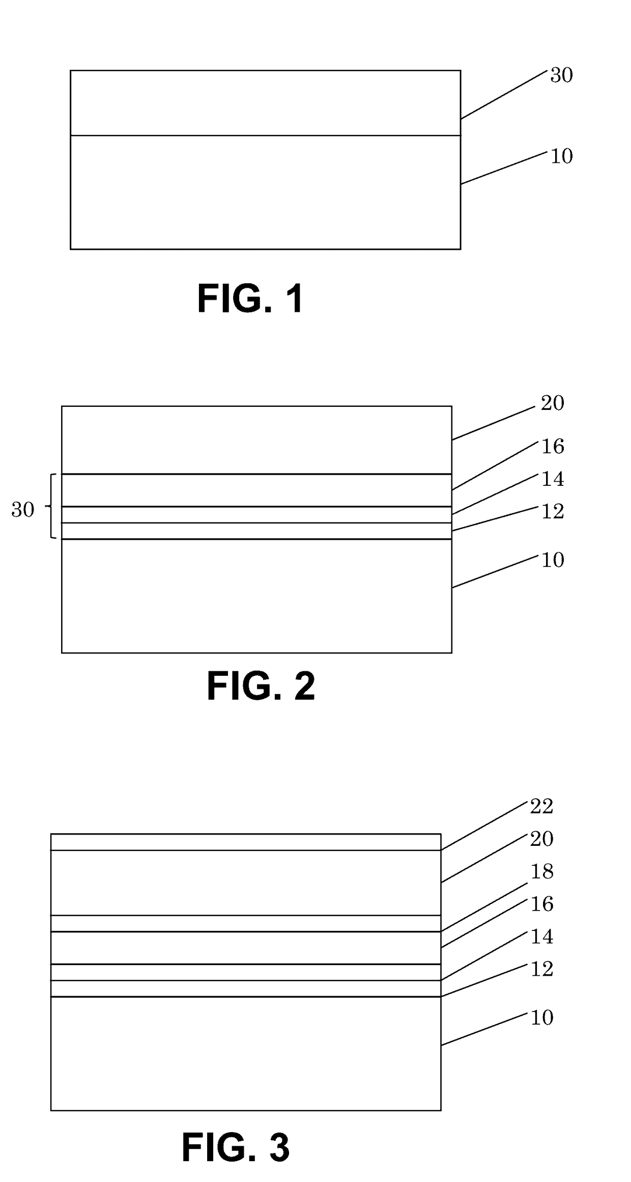
[0048]Cutting tests were performed in connection with a target material of American Iron and Steel Institute (AISI) 4340 hardened steel with severe interruptions. The inserts used for testing were CNMA432 carbide turning inserts, coated with nanostructured coatings in multi-layered form (individual nanostructured layers 12, 14, and 16) and with additional layers 18, 20, and 22 as described above. A benchmark test was performed using the same type of insert (same style and grade) coated with conventional coating techniques with similar chemistry but micron-sized grains in each of the coating layers. The workpiece used was a material with a diameter of 6.0″, with four deep, V-shaped slots in the peripherals to provide interruptions for testing, along with four ⅜″ diameter through-holes evenly distributed on the end surface. Machining conditions were as follows:

[0049]Surface speed: 400 SFM

[0050]Feed rate: 0.0004 IPR

[0051]Depth of cut: 0.01″

[0052]Dry / wet: with cutting fluid

[0053]Failure...


PUM

PropertyMeasurementUnit
Fractionaaaaaaaaaa
Thicknessaaaaaaaaaa
Thicknessaaaaaaaaaa

Abstract

A coating for carbide substrates employs a nanostructured coating in conjunction with a non-nanostructured coating. The nanostructured coating is produced by the addition of a refining agent flow, particular hydrogen chloride gas, during deposition, and may be produced as multiple individual nanostructured layers varying functional materials in a series. The combination of a nanostructured coating and non-nanostructured coating is believed to produce a cutting tool insert that exhibits longer life. Pre-treating the substrate with a mixture of compressed air and abrasive medium prior to coating the substrate and post-treating the coated substrate with a mixture of water and abrasive medium after the coating process is believed to further enhance the wear resistance and usage life of the cutting tool.

Description

CROSS-REFERENCE TO RELATED APPLICATIONS[0001]This application is a continuation-in-part of U.S. patent application Ser. No. 13 / 450,787, filed on Apr. 19, 2012, and entitled “Nanostructured Multi-Layer Coating”, which claims priority from U.S. provisional patent application No. 61 / 601,081, filed Feb. 21, 2012, and entitled “Nanostructured Multi-Layer Coating on Carbides.” This application also claims priority from U.S. provisional patent application 62 / 300,634, filed Feb. 26, 2016, and entitled “Coated Carbide Cutting Tools.” Such applications are incorporated by reference in their entireties.STATEMENT REGARDING FEDERALLY SPONSORED RESEARCH OR DEVELOPMENT[0002]Not applicable.BACKGROUND OF THE INVENTION[0003]Coatings are effective for improving the performance of various materials, such as for achieving better wear resistance and corrosion resistance. Common applications where a coating is applied to a substrate to improve wear resistance of the substrate material include cutting tool...

Claims


Application Information

Patent Timeline
IPC IPC(8): B23B27/14C23C16/56C23C16/34C23C16/36C23C16/02C23C16/40
CPCB23B27/148C23C16/0254C23C16/403C23C16/34B23B2224/04C23C16/56B23B2228/105B23B2224/36B23B2228/04C23C16/36B82Y30/00B82Y40/00Y10T428/24355Y10T428/265C23C28/044C23C28/00
Inventor JIANG, WENPINGKIMMEL, MIKEMALSHE, AJAY P.
Owner P&S GLOBAL HLDG LLC
Why Eureka
Try Eureka