

Carbon nanotube-based thermal interface materials and methods of making and using thereof
a technology of thermal interface materials and carbon nanotubes, which is applied in the direction of electrical apparatus construction details, modification by conduction heat transfer, vacuum evaporation coating, etc., can solve the problems of high contact area at such interfaces between surfaces, difficulty in growing very long cnts on metal substrates, and early termination of tube growth, etc., to achieve high levels of compliance
- Summary
- Abstract
- Description
- Claims
- Application Information
AI Technical Summary
Benefits of technology
Problems solved by technology
Method used
Image

Examples
example 1
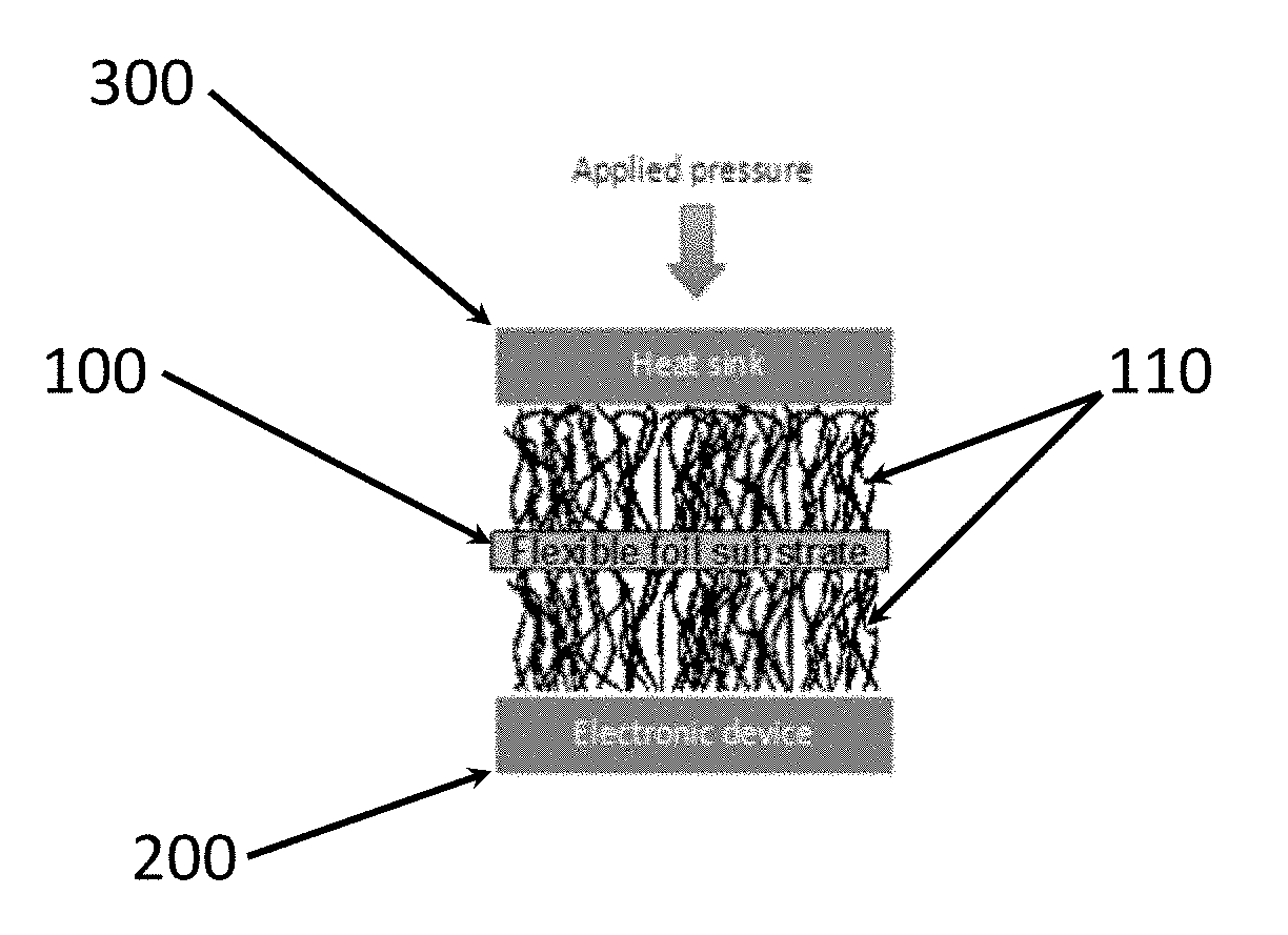
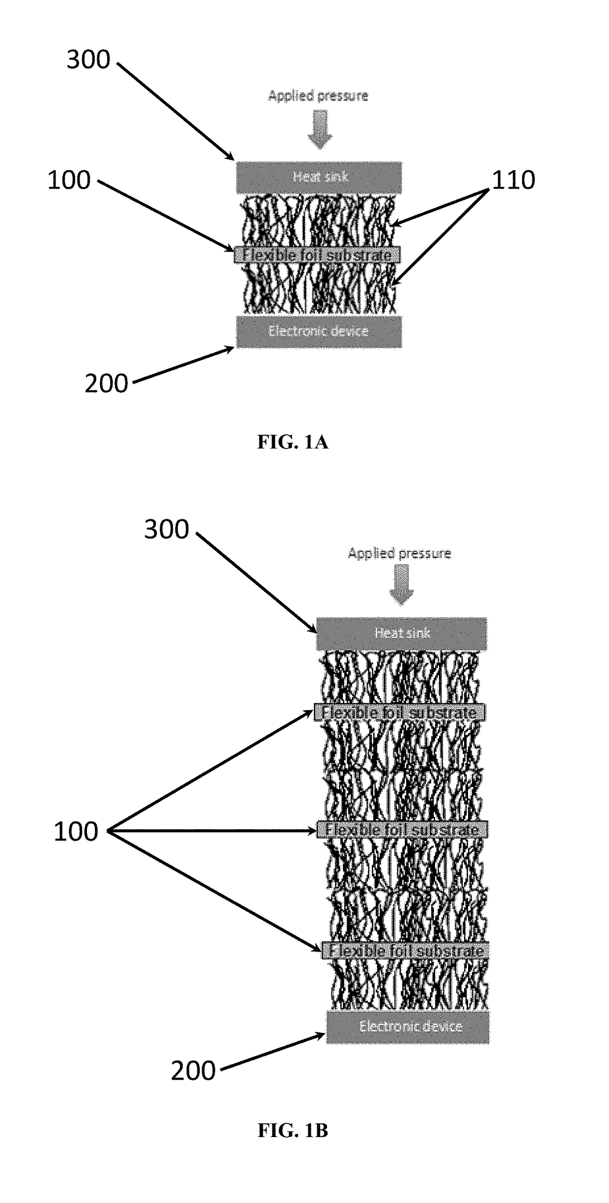
red / Multitiered CNT-Based Thermal Interface Materials (TIMs)
[0137]Methods:
Thermal Measurement System Design
[0138]Heat transfer properties for all test specimens were evaluated using a test fixture (not shown) designed and built based on the methods described in ASTM D5470 “Standard Test Method for Thermal Transmission Properties of Thermally Conductive Electrical Insulation Materials.” It not only allows for deformation of the test specimens but also incorporates a vacuum chamber to minimize conductive and convective heat losses. The vacuum chamber was constructed of stainless steel with an acrylic door, and is capable of maintaining vacuum in the 10−5 torr range. The vacuum chamber sits on the reaction plate of a 1000 lb load frame, with all feedthroughs near the top of the chamber. Thermocouples were fed via a pair of Omega 4-pair feedthroughs (8 thermocouples possible). The cooling tubes possess bulkhead fittings with o-ring seals. The power for the heaters were controlled via a ...
example 2
red / Multitiered CNT-Based Thermal Interface Materials (TIMs) Containing Polymer or Adhesive
[0158]CNT arrays were grown to nominally 100 μm thickness and fully infiltrated with a soft polyurethane polymer. The thermal resistance of each individual pad was measured using a modified ASTM D570 stepped bar apparatus.
[0159]The individual samples were stacked using various methods, and the thermal resistance of the resulting stack was measured in the same manner as the single tiers.
[0160]First, two individual array samples with measured thermal resistances of 1.37 and 1.5 cm2-K / W respectively were stacked on top of one another. Solvent known to dissolve the polymer that was used to infiltrate the array was placed between the stacks to place the interface in a liquid state. The resulting stack was allowed to dry under pressure until the solvent was fully evaporated. The stack was then measured in the stepped bar system with a resulting resistance of 1.5 cm2-K / W. In this example, the thickne...
example 3
red / Multitiered CNT-Based Thermal Interface Materials (TIMs)
[0162]Sample Fabrication:
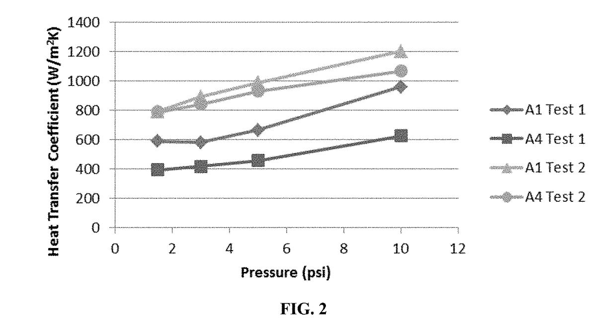
[0163]Vertically aligned carbon nanotube (CNT) arrays were grown on aluminum foil as the base substrate. Both sides of 50 μm thick aluminum foil were coated with an iron catalyst layer and the CNTs were grown via low pressure chemical vapor deposition with acetylene and hydrogen as precursor gases and growth being performed at 630° C. in order to stay below the melting temperature of the Al substrate. CNTs were grown to 7-10 μm on both sides of the substrate with an 8 minute growth time. One-tier CNT-based thermal interface material (non-stacked) and two- and four-tiered (formed by stacking two or four double-sided CNT arrays) CNT-based thermal interface materials (TIMs) having an area of 1 cm×1 cm were prepared for testing.
[0164]Testing Methods:
[0165]In order to measure the thickness, compression, and rebound of the one and three-tiered TIMs prepared, a Precision Thickness Gauge—FT3V by Hanatek® In...
PUM
| Property | Measurement | Unit |
|---|---|---|
| pressure | aaaaa | aaaaa |
| temperature | aaaaa | aaaaa |
| pressures | aaaaa | aaaaa |
Abstract
Description
Claims
Application Information