Method and device for producing 3D moulded parts by means of a layer construction technique

a layer construction and 3d modeling technology, applied in the direction of additive manufacturing, additive manufacturing processes, solids additive manufacturing, etc., can solve the problems of powder to “age”, powder to exceed the cost of standard polyamide by a factor of 20-30, and the bulk density of the particle material bed cannot exceed a certain amount, so as to achieve the effect of higher boiling poin

Active Publication Date: 2017-12-14
VOXELJET AG
View PDF5 Cites 57 Cited by
  • Summary
  • Abstract
  • Description
  • Claims
  • Application Information

AI Technical Summary

Benefits of technology

[0094]The following approach may be taken. Preferably, the same temperature or locally different temperatures are set or generated in the applied construction material. Preferably, a temperature is set in the jacket that is below the sintering temperature of the construction material in this area. It is also possible to adjust or achieve a specific temperature profile, by forming and placing the jacket accordingly. Preferably, a temperature profile is generated, in the applied construction material, that is characterised by a temperature distribution of low: higher: still higher (T1<T2<T3) in the following areas: area outside the jacket: jacket area: area within the jacket (jacket <jacket area <a rea within the jacket) according to FIG. 6.
[0095]On the other hand, the temperature achieved in the construction field is controlled directly by the energy input, with the jacket influencing the local temperature adjustment. Advantageously, heat or energy input may be performed in a uniform or locally differing manner across the construction field.
[0096]As shown, the temperature adjustment can be controlled by the construction of the jacket and is controllable by the introduction of the absorber. Preferably, an absorber is used for the jacket which has a higher boiling point than the absorber used for the 3D moulded part. The amount of the absorber or absorbers is preferably controlled via greyscale values of the print head or via dithering methods.
[0097]Known print heads with suitable technology are used to apply the liquid and the absorber. The liquid may be selectively applied by means of one or more print heads.
[0098]Preferably, the print head or print heads are adjustable in terms of drop mass. The print head or print heads may selectively apply the liquid in one or both directions of movement. The method achieves that the particulate construction material is selectively solidified, preferably selectively solidified and sintered.
[0099]In the construction process, the construction material and the absorber are cyclically applied. For this purpose, the construction field is lowered by the desired layer thickness or the application units are raised correspondingly. These operations are cyclically repeated. In a corresponding manner, the basic temperature in the construction material is also adjusted, and then the temperature is cyclically increased within a temperature band above the basic temperature in selected areas and decreased again. The temperature band is determined by the material. Depending on the selection of the construction material, the temperature band preferably extends within a range from 0 to −50 K, 0 to −30 K, 0 to −20 K and 0 to 10 K, from the melting point of the construction material.

Problems solved by technology

However, it has the disadvantage that the particulate material bed cannot exceed a certain bulk density, which is usually 60% of the particle density.
This is not only a relatively time-consuming process due to the single-droplet input, but it also causes many process-related problems, which are given, for example, by the inevitable shrinkage of the liquid volume during solidification.
This results in selective heating within the layer beyond the melting point and, consequently, in selective solidification.
Due to the manufacturing process, however, costs are high and may exceed the cost of standard polyamide by a factor of 20-30.
This causes the powder to “age” and limits its use in subsequent processes.
A low recycling rate results, which has a negative effect on process costs.
The known HSS methods have a multitude of disadvantages concerning, on the one hand, the recycling rate and, on the other hand, process costs, consequently increasing the cost per piece and making it rather expensive.
In particular, the aging of the powder is a crucial problem, and the resulting low recycling rate is a great hindrance for this process to become more widespread.
However, this approach has narrow limits, because most powders do not have a sufficient “sintering window” to be safely processed.
This means that stable process parameters are hard to find for these powders.
However, for process-related reasons alone, aging cannot be fully restricted, because part of the solidification reaction occurs by a secondary reaction of the polymer.
Curbing this secondary reaction would mean essential limitations in strength.
One problem with known HSS methods is the adjustment of advantageous process conditions, such as, for example, the temperature windows with respect to the particulate materials used.
The HSS process combines a great number of process parameters and the 3D printing machines used therein have a great number of constructive features and components, which makes it difficult to combine suitable components and adjust an advantageous or improved process sequence allowing improved process conditions.
In many cases, it is impossible to determine what constructive changes are required in order to achieve acceptable process results and obtain high-quality 3D parts and / or optimise the process.
Another problem in adjusting the process conditions is to combine the process conditions such that, on the one hand, a sufficiently strong component is manufactured with desired and advantageous properties, while at the same time subjecting the particulate material that is not to solidify to process conditions enabling easy unpacking.
One problem in this regard is that the surrounding material solidifies too much in the process and is therefore difficult to remove from the component requires increased effort to do so.
Another problem and a further disadvantage in the manufacture of 3D moulded parts by HSS are temperature gradients which occur across the surface of the component to be manufactured and in the construction material surrounding the component up to the peripheral areas of the construction platform.
This involves disadvantages that either interfere with the process itself or result in drawbacks to quality, e.g. curling, warping, inaccuracy of the moulded part or increased wastage.
Due to the emission and thermal conduction into the surrounding particulate material, the edge of the moulded part cools off quicker than internal regions, which results in undesired temperature differences in the moulded part, along with the above-mentioned disadvantages.

Method used


Image

  • Method and device for producing 3D moulded parts by means of a layer construction technique
  • Method and device for producing 3D moulded parts by means of a layer construction technique
  • Method and device for producing 3D moulded parts by means of a layer construction technique

Examples


example 1

Device Comprising an Inkjet Print Head with a Binary Droplet Size

[0192]The injket print heads common in 3D printing deposit one droplet on a dot in the raster of the print area. The size of said droplet is adjusted once.

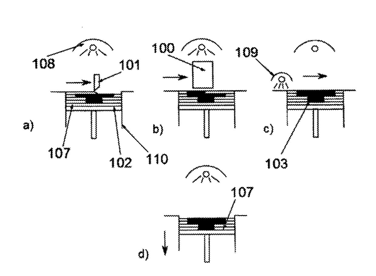
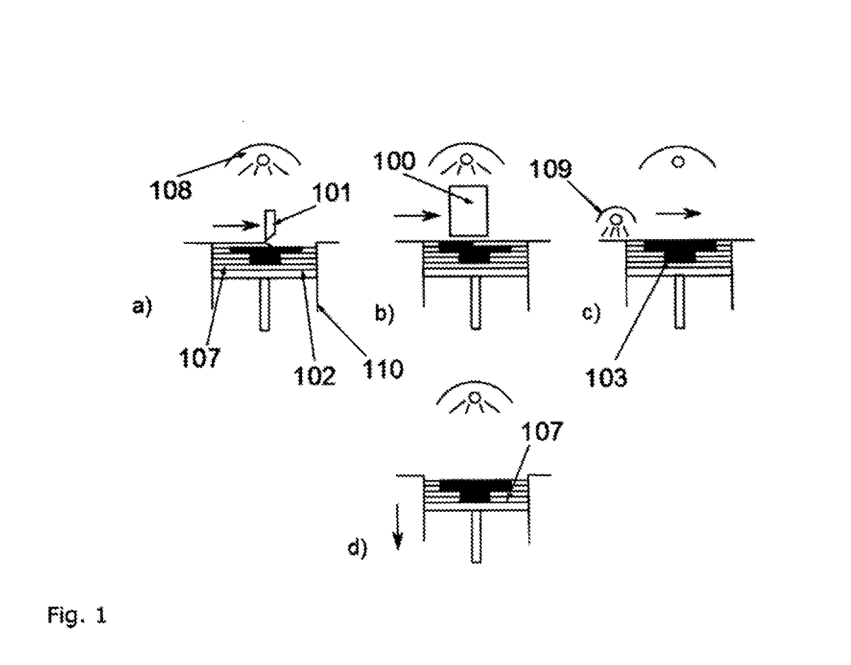
[0193]During printing, in the method according to the invention, a respective cross-sectional image of the desired components (103) is printed using absorber, said image being adapted to the construction height. In this case, the image is printed in an intensity ensuring definite sintering of the particles during the pass of the sintering lamp. As described above, unprinted areas will remain unsintered. The necessary amount of liquid imprinted per raster dot in this case will be considered black in the following.

[0194]In the process, a jacket (301) is printed around the component, said jacket (301) representing a greyscale value, i.e. containing less absorber based on the local average. As preferred according to the invention, the jacket (301) is determined from the ...

example 2

Greyscale Print Head

[0198]A device comprising a greyscale print head is more precise in use. These print heads are common and well-known in the print media sector. They allow the apparent resolution to be increased in this sector, thus achieving a better image quality.

[0199]In 3D printing, this increase in resolution does not have a direct effect. However, according to the invention, this technique can be used to introduce different amounts of liquid in the component (103) and jacket (301) areas. For instance, the amount of liquid introduced in the jacket area may be set to 50% of that introduced in the component area. Data transmission is effected by the use of a polychromatic raster bitmap. As a minimum, another raster bitmap can be defined which contains the data for the peripheral area. The electronic system of the print head then considers the respective bits as greyscale information.

example 3

Material System Comprising a Separating Agent

[0200]Further essential degrees of freedom result for the invention if several different liquids are used for printing.

[0201]For this purpose, the device according to the invention has to be extended. A second print head (508) is used which can print the second absorber. In this case, the data path in the control unit of the machine need not be changed. The data is divided up electronically before the respective print head. This print head need not be a separate physical unit, but can be part of the print head (100) of the device.

[0202]The second absorber liquid may contain an oil, for example, which serves as a separating agent. This separating agent deposits between the individual particles and prevents their contact with the molten base material. In the case of polyamide 12 as base material, a certain amount of silicone oil in the printing liquid may serve as separating agent. This oil must be maintained as a suspension with the rest o...


PUM

PropertyMeasurementUnit
wavelength rangeaaaaaaaaaa
thicknessaaaaaaaaaa
thicknessaaaaaaaaaa

Abstract

The invention relates to a method and an apparatus for producing three-dimensional models by layering in a high-speed sintering process.

Description

[0001]The invention relates to a method and a device for producing 3D models by means of a layer construction technique.[0002]European Patent EP 0 431 924 B1 describes a process for producing three-dimensional objects, based on computer data. In the process, a thin layer of particulate material is deposited on a platform and has a binder material selectively printed thereon by means of a print head. The particulate region with the binder printed thereon bonds and solidifies under the influence of the binder and, optionally, an additional hardener. Next, the platform is lowered by one layer thickness into a construction cylinder and provided with a new layer of particulate material, the latter also being printed on as described above. These steps are repeated until a certain desired height of the object is achieved. Thus, the printed and solidified regions form a three-dimensional object.[0003]Upon completion, the object made of solidified particulate material is embedded in loose pa...

Claims


Application Information

Patent Timeline
Patent Type & Authority Applications(United States)
IPC IPC(8): B29C64/165B29C64/35B29C67/00
CPCB29C64/165B29C67/00B29C64/35B33Y10/00B33Y30/00B29C64/295B29C64/357B29C64/264B29C64/153B29C64/393B33Y70/10B33Y50/02B33Y40/00B29C35/0288B29K2105/251C01P2004/61B29K2877/00B29K2509/02B29K2509/08
Inventor EDERER, INGOGUNTHER, DANIELGUNTHER, JOHANNESSCHECK, CHRISTOPH
Owner VOXELJET AG
Why Eureka
Try Eureka